A spline gear rubbing positioning tool

A technology for positioning tooling and splines, applied in the mechanical field, can solve problems such as phase angle not being detected in time, internal spline deformation, low pass rate, etc., to avoid repeated debugging, improve efficiency, and save time.

Active Publication Date: 2017-01-25
浙江汇丰汽车零部件股份有限公司
View PDF6 Cites 0 Cited by
  • Summary
  • Abstract
  • Description
  • Claims
  • Application Information

AI Technical Summary

Problems solved by technology

[0003] The phase angle is usually controlled and manufactured during the production of extruded external splines, but this manufacturing method will cause deformation of the internal splines and problems that cannot be detected in time when the phase angle changes, and the pass rate is low

Method used


Image

  • A spline gear rubbing positioning tool

Examples


Embodiment Construction

[0020] The following are specific embodiments of the present invention and in conjunction with the accompanying drawings, the technical solutions of the present invention are further described, but the present invention is not limited to these embodiments.

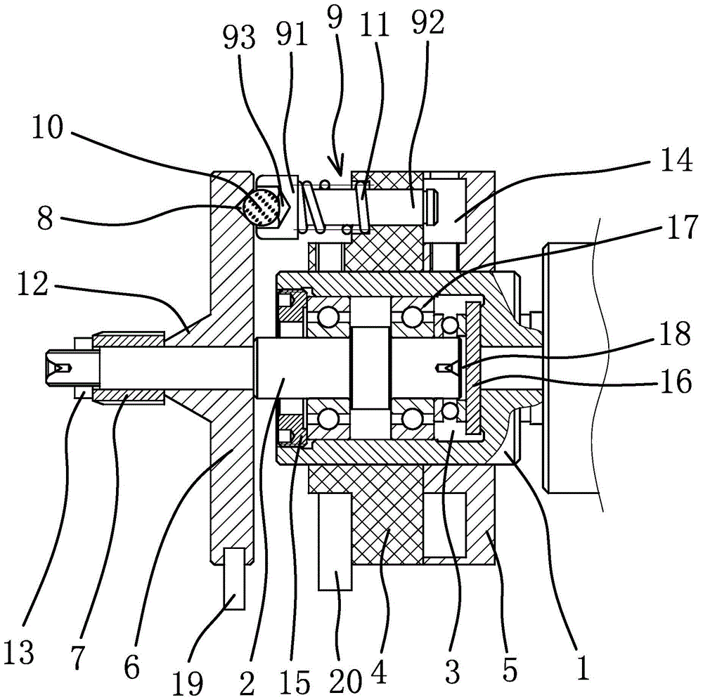
[0021] Such as figure 1 As shown, the spline gear rubbing positioning tool includes a connecting rod 1, a rotating shaft 2, an adjusting disc 4, a dial 5, a positioning disc 6, a spline mandrel 7, a positioning pin 9, a steel ball 10, a spring 11, and the like.

[0022] The front end of the connecting rod 1 has a cavity 3, the rear end is used to be fixedly connected with the workbench, and the outer wall of the front end of the connecting rod 1 is fixedly connected with an adjusting disc 4 and a dial 5 by welding. The rear end of the rotating shaft 2 is located in the cavity 3, and the circumferential outer wall of the rotating shaft 2 located in the cavity 3 has an annular protrusion. The opening of the cavity 3 is fixed...


PUM


Abstract

The invention provides a spline gear rolling locating tool and belongs to the technical field of machines. The problem that the qualification rate of existing spline gear rolling is low is solved through the spline gear rolling locating tool. The spline gear rolling locating tool comprises a connection rod and a rotation shaft. A cavity is formed in the front end of the connection rod. The rear end of the connection rod is fixedly connected with a workbench. An adjusting disc and a dial disc are fixedly connected to the outer side wall of the front end of the connection rod. The rear end of the rotation shaft is located in the cavity. The rotation shaft is fixed to the connection rod in the axial direction. A locating disc is fixedly connected to the rotation shaft. A spline mandrel is detachably and fixedly connected with the front end of the rotation shaft. The adjusting disc is located between the dial disc and the locating disc. A groove is formed in the side, close to the adjusting disc, of the locating disc. A locating bolt penetrates through the adjusting disc. A steel ball is arranged at the end, close to the locating disc, of the locating bolt which is sleeved with a spring. On end of the spring is abutted against the locating bolt, and the other end of the spring is abutted against the adjusting disc. The steel ball can be embedded in the groove under the elasticity effect of the spring. The spline gear rolling locating tool has the advantage of improving the product percent of pass.

Description

technical field [0001] The invention belongs to the technical field of machinery and relates to a spline gear rubbing positioning tool. Background technique [0002] The steering system of an automobile includes a steering shaft. The input end of the steering shaft is connected to the steering wheel through the cooperation of external splines and internal splines, and the output end of the steering shaft is also connected to the steering universal joint through the cooperation of external splines and internal splines. To ensure the consistency of the steering wheel during assembly, the phase angle will be increased at the input and output ends of the steering shaft, and it is necessary to ensure the consistency of the phase angle. [0003] The phase angle is usually controlled and manufactured during the production of extruded external splines. However, this manufacturing method will cause deformation of the internal splines and problems that cannot be detected in time when ...

Claims


Application Information

Patent Timeline
Patent Type & Authority Patents(China)
IPC IPC(8): B21H5/00
Inventor 董西杰
Owner 浙江汇丰汽车零部件股份有限公司
Why Eureka
Try Eureka