Hydraulic buffer

A hydraulic buffer and internal pressure technology, which is applied in the field of hydraulic buffers, can solve the problems that the buffering effect cannot be realized, and achieve the effect of prolonging the service life and reducing the amount of maintenance

Inactive Publication Date: 2012-09-19
宁波科赛特气动科技有限公司
View PDF0 Cites 5 Cited by
  • Summary
  • Abstract
  • Description
  • Claims
  • Application Information

AI Technical Summary

Problems solved by technology

[0005] It takes a period of time for the currently used oil pressure buffer to be stable from the impact of the force, which results in the inability to achieve the buffering effect on repeated impact movements in a short period of time, that is, how to reduce the buffering time of the buffer is The technical problem that the present invention needs to solve

Method used


Image

  • Hydraulic buffer
  • Hydraulic buffer
  • Hydraulic buffer

Examples


Embodiment Construction

[0028] The specific technical solutions of the present invention will be described in detail below in conjunction with the accompanying drawings. The specific embodiments of the present invention are only exemplary, and can only be used to explain the present invention rather than limit the present invention.

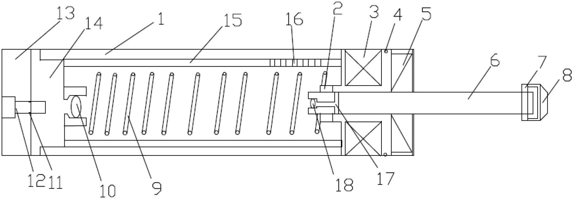
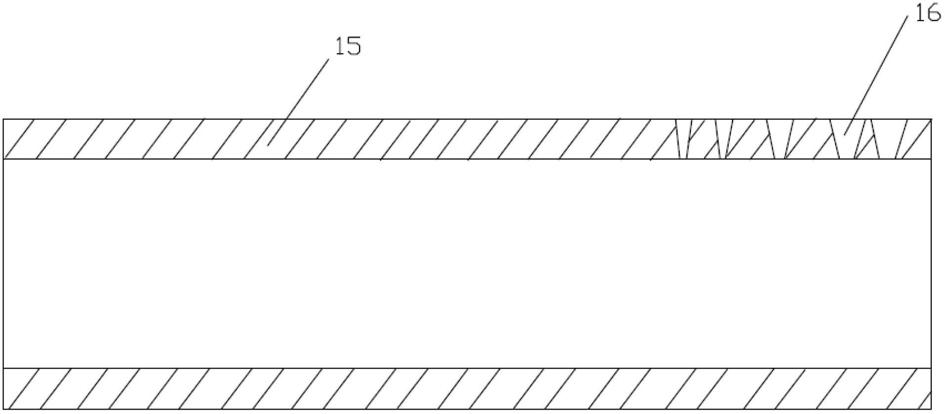
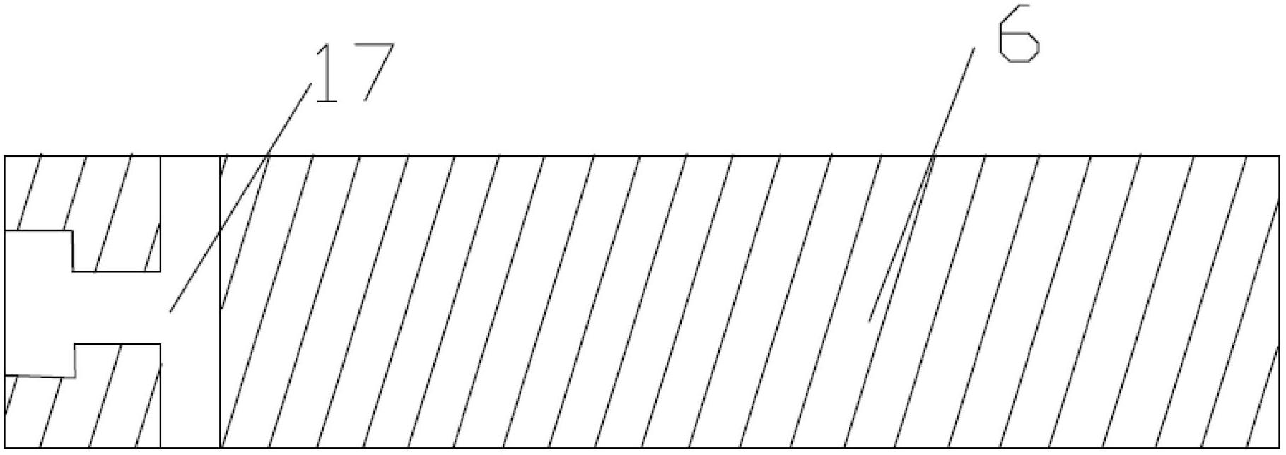
[0029] Such as Figure 1-Figure 3 Shown, the present invention is achieved through the following technical solutions:

[0030] An oil pressure buffer, including a housing 1, a rear cover 14, an oil seal 5, an internal pressure cylinder 15, a piston 2, a piston rod 6, an impact head 7, a bearing 4, a spring 9, a pressure accumulator 3, and a flow adjustment plug 12 and the flow adjustment knob 13; the end of the piston rod 6 located in the internal pressure cylinder 15 is provided with an oil storage chamber 17, and the oil storage chamber 17 is opened at the axis of the end of the piston rod, and the opening is the same as that of the internal pressure cylinder The bac...


PUM


Abstract

The invention relates to a hydraulic buffer which comprises a casing, a rear cover, an oil seal, an inner pressure cylinder block, a piston, a piston rod, an impact head, a bearing, a spring, an accumulator, a flow adjusting bolt and a flow adjusting knob. An oil storage cavity is reserved at the end of the piston rod located inside the inner pressure cylinder block. Two check valves are arranged at the rear cover and the end of the piston rod respectively. The piston rod with the check valve is charged into the casing and is closed through the oil seal. The accumulator is then charged in, and the inner pressure cylinder block is charged into the casing. The spring is charged into the inner pressure cylinder block, and the casing is closed through the rear cover. The flow adjusting bolt and the flow adjusting knob are mounted on the rear cover. The inner pressure cylinder block is provided with an oil hole.

Description

technical field [0001] The invention belongs to the field of shock absorbers, in particular to an oil pressure buffer. Background technique [0002] The oil pressure buffer is a hydraulic device that converts the impact kinetic energy into the heat energy of the hydraulic oil, and realizes the linear deceleration of the object and finally a smooth stop. [0003] In the field of decompression, the spring, rubber, and cylinder cushioning continue at the lowest linear level at the beginning of the moving object's stroke, and the reaction force gradually increases as the stroke increases. Absorbed instead of temporarily stored, the moving object eventually inevitably rebounds greatly, causing mechanical damage. At present, dampers are used as shock absorbing devices, but the defects of the damper in the oil hole system will cause the moving object to stop instantly with the peak reaction force at the beginning of the shock absorbing stroke, causing a huge mechanical shock, and ...

Claims


Application Information

Patent Timeline
Patent Type & Authority Applications(China)
IPC IPC(8): F16F9/18F16F9/32
Inventor 沈皓
Owner 宁波科赛特气动科技有限公司
Why Eureka
Try Eureka