Unlock instant, AI-driven research and patent intelligence for your innovation.
Device and method for measuring brewster angle
What is Al technical title?
Al technical title is built by PatSnap Al team. It summarizes the technical point description of the patent document.
A technology of Brewster's angle and measuring device, which is applied in the direction of polarization influence characteristics, can solve the problems of Brewster's angle error and inability to do quantitative analysis, and achieve the effect of easy observation and simple and ingenious production
Active Publication Date: 2014-09-03
CHINA AGRI UNIV
View PDF8 Cites 0 Cited by
Summary
Abstract
Description
Claims
Application Information
AI Technical Summary
This helps you quickly interpret patents by identifying the three key elements:
Problems solved by technology
Method used
Benefits of technology
Problems solved by technology
[0006] The technical problem to be solved by the present invention is: the measurement of Brewster's angle by the existing instruments by human eyes has a large error, and it is impossible to achieve quantitative analysis in the true sense
Method used
Image
Click on the blue label to locate the original text in one second.
Reading with bidirectional positioning of images and text.
Examples
Embodiment 1
[0056] Install the measuring device according to the above steps, place the prism on the stage, and the data measured according to the above method are as follows:
[0057] Table 1 Spectrometer data measured by two-way approximation
[0058]
[0059] Table 2 Readings of the vernier at the position of the reflected ray reaching Brewster's angle
[0060]
[0061] Table 3 Readings at the position where the telescope is aligned with the collimator
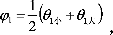
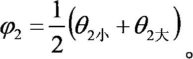
[0062] Left cursor reading θ 1平
Right cursor reading θ 2平
231°30′
51°30′
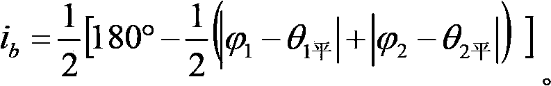
[0063] The size i of Brewster's angle calculated from the above data b for:
[0064]
[0065] n = tani b =1.62
[0066] Compared with the actual refractive index n=1.64, the measured refractive index of the triangular prism deviates very little.
Embodiment 2
[0068] Install the measuring device according to the above steps, place the artificial marble on the stage, and the data measured according to the above method are as follows:
[0069] Table 4 Spectrometer data measured by two-way approximation method
[0070]
[0071] Table 5 Readings of the vernier at the position of the reflected ray reaching Brewster's angle
[0072]
[0073] Table 6 Readings at the position where the telescope is aligned with the collimator
[0074] Left cursor reading θ 1平
Right cursor reading θ 2平
231°0′
70°0′
[0075] The size i of Brewster's angle calculated from the above data b for:
[0076]
[0077] n = tani b =1.532
[0078] Compared with the actual refractive index n=1.530 of the artificial marble, the measured refractive index in this embodiment deviates very little.
[0079] According to the above two embodiments, the Brewster's angle error measured by the method of the present invention is ...
PUM
Abstract
The invention relates to a device and a method for measuring brewster angle; the device comprises a light source, a spectrometer and polarizing elements, wherein the spectrometer comprises a parallel light pipe, a telescope and an object stage; a to-be-measured medium is placed on the object stage; incident light emitted by the light source is emitted from the parallel light pipe to the to-be-measured medium; emergent light is reflected from the to-be-measured medium and is input to the telescope; the front part of the parallel light pipe is provided with a first polarizing element, of which a non-opaque axle is vertical to the incident light, and a second polarizing element, of which the non-opaque axle is parallel to an incident plane; and the device is used for measuring in the method. According to the device and the method for measuring brewster angle, the brewster angle is measured through the spectrometer; the polarizing elements are arranged in front of the parallel light pipe of the spectrometer, wherein two non-opaque axles of the polarizing elements are vertical mutually; the brewster angle can be observed in the telescope easily by two generated rays with relatively large contrast brightness; therefore, the brewster angle of the rays incident to the to-be-measured medium can be measured precisely.
Description
technical field [0001] The invention belongs to the field of measuring Brewster's angle, in particular to a measuring device and method for Brewster's angle. Background technique [0002] In 1812, Scottish physicist Brewster (D. Brewster, 1781-1868) found that the degree of polarization of reflected light depends on the angle of incidence when studying the degree of polarization of reflected light. When the angle of incidence i b and refraction angle r 0 The sum is equal to 90°, as figure 1 As shown, that is, when the reflected light and the refracted light are perpendicular to each other, the reflected light becomes linearly polarized light whose vibration direction is perpendicular to the incident plane. [0003] At present, the measurement of Brewster's angle is judged according to when the reflected light reaches the linear polarization state, such as figure 2 As shown, a polarizer is installed on the side of the reflected light to analyze the polarization, and the p...
Claims
Application Information
Patent Timeline
Application Date:The date an application was filed.
Publication Date:The date a patent or application was officially published.
First Publication Date:The earliest publication date of a patent with the same application number.
Issue Date:Publication date of the patent grant document.
PCT Entry Date:The Entry date of PCT National Phase.
Estimated Expiry Date:The statutory expiry date of a patent right according to the Patent Law, and it is the longest term of protection that the patent right can achieve without the termination of the patent right due to other reasons(Term extension factor has been taken into account ).
Invalid Date:Actual expiry date is based on effective date or publication date of legal transaction data of invalid patent.

