

Dimming devices and displays
A technology of a dimming device and a display, which is applied to static indicators, optics, instruments, etc., can solve the problem of low utilization rate of transmission backlight sources, and achieve the effect of improving the utilization rate of backlight.
- Summary
- Abstract
- Description
- Claims
- Application Information
AI Technical Summary
Problems solved by technology
Method used
Image

Examples
Embodiment 1
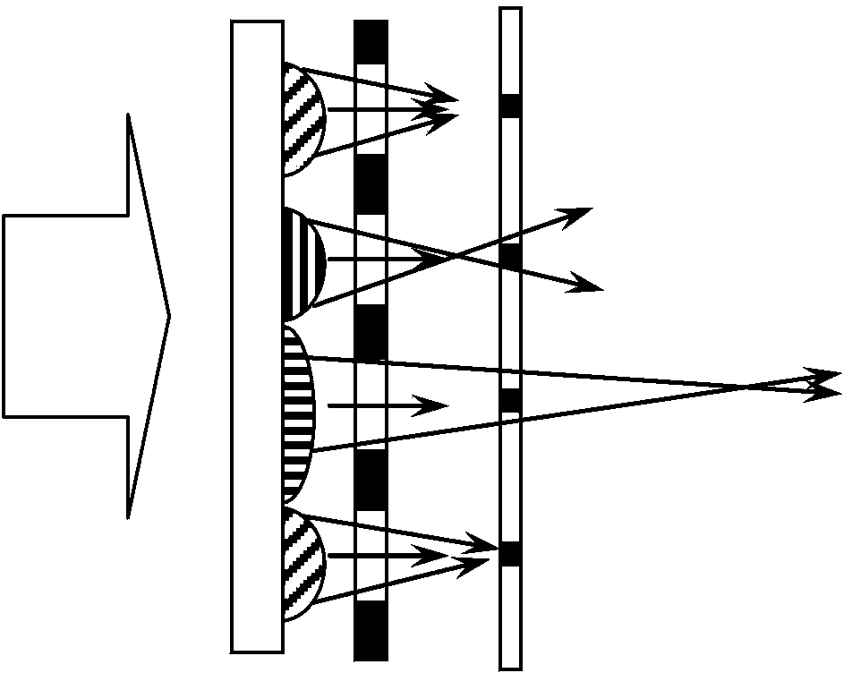
[0053] In the present invention, Embodiment 1 of colorizing the lens-type dimming device is as follows: figure 2 As shown, in this embodiment 1, the colorization of the entire dimming device is realized by colorizing the droplet lens.
[0054] Specifically, three droplet lenses are set in one pixel unit, and the three droplet lenses are colored into three colors of red (R), green (G), and blue (B) respectively (because the colors cannot be displayed in the drawings ,exist figure 2 The middle oblique stripes indicate that the area is red, the vertical stripes indicate that the area is green, and the horizontal stripes indicate that the area is blue; the stripes in the following figures are the same as figure 2 The meaning is the same in the above, and will not be described in detail below), and the color and brightness displayed on a pixel unit are obtained through the combination of three colors of different intensities passing through the light. A color display panel wit...
Embodiment 2
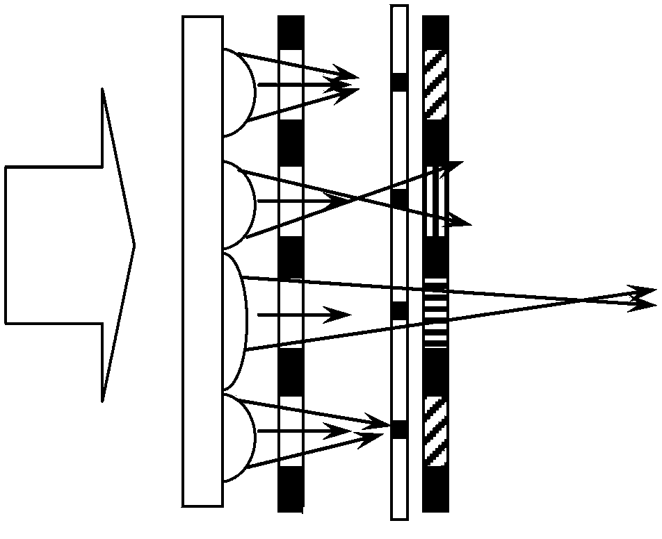
[0056] In the present invention, Embodiment 2 of colorizing the lens-type dimming device is as follows image 3 As shown, in this embodiment 2, the colorization of the entire dimming device is realized by placing color filters. The position of the color distribution (for example, the position of R, G, B distribution) corresponds to the droplet lens.
[0057] Specifically, a color filter is placed between the top electrode and the baffle, or a color filter is placed outside the baffle, similar to the TFT-LCD array substrate, and a pixel unit on the color filter is provided with red, There are three sub-pixel units of green and blue, and each sub-pixel unit corresponds to a droplet lens. The light transmitted by the droplet lens is filtered into the light of the corresponding color, which is obtained by combining the transmitted light of three colors with different intensities. The color and brightness displayed on a pixel unit. A color display panel with corresponding resolut...
Embodiment 3
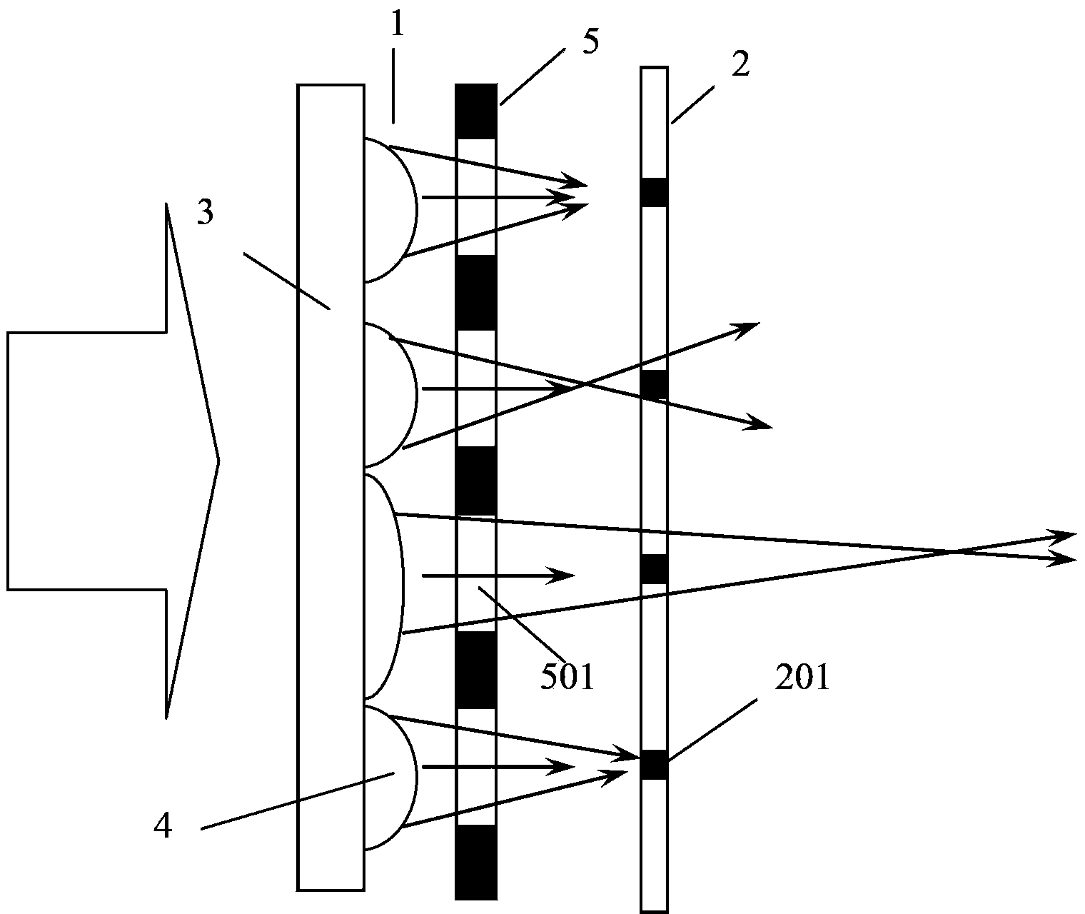
[0059] In the present invention, Embodiment 3 of colorizing the lens-type dimming device is as follows Figure 4 As shown, in the third embodiment, the colorization of the entire dimming device is realized by colorizing the light-transmitting area of the baffle. The colored colors are distributed in the light-transmitting area of the baffle, and each light-transmitting area of the baffle is divided into two colors, and the same color is set on both sides of each light-shielding area 201 . And the overall position of each color corresponds to the droplet lens. Optionally at this time, the area of the light-shielding region 201 of the baffle is smaller than the area of the corresponding droplet lens.
[0060] Specifically, similar to Embodiment 2, filters of various colors are arranged in the light-transmitting area of the baffle, and three sub-pixel units of red, green, and blue are formed in one pixel unit on the baffle, and each sub-pixel unit is connected with ...
PUM
 Abstract
Description
Claims
Application Information