Optical film, preparation method thereof and display device

An optical diaphragm and diaphragm technology, applied in optics, nonlinear optics, instruments, etc., can solve problems such as the ability to limit the utilization rate of DBEF backlight, waste, etc., and achieve the effect of improving the utilization rate of backlight

Active Publication Date: 2022-07-29
HKC CORP LTD
View PDF30 Cites 0 Cited by
  • Summary
  • Abstract
  • Description
  • Claims
  • Application Information

AI Technical Summary

Problems solved by technology

However, the polarized light reflected by DBEF needs to undergo many times of reflection and refraction to convert part of the energy into the target polarization direction. During this period, the energy is repeatedly absorbed by each layer of diaphragm, resulting in a lot of waste, which limits the ability of DBEF to improve the utilization rate of backlight.

Method used


Image

  • Optical film, preparation method thereof and display device
  • Optical film, preparation method thereof and display device
  • Optical film, preparation method thereof and display device

Examples


no. 1 example

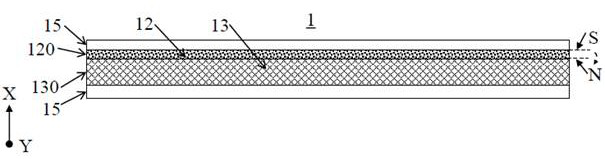
[0031] figure 1 A schematic structural diagram of the optical film provided by the first embodiment of the present application is shown.

[0032] like figure 1 As shown, the first embodiment of the present application provides an optical film 1, which includes a light-transmitting base material 11, magnetic powder 12 and a magneto-optical medium 13 disposed in the light-transmitting base material 11, and the magnetic powder 12 is used to form a surface magnetic field, The magneto-optical medium 13 is located in a surface magnetic field, so that the polarization direction of the linearly polarized light is rotated after passing through the magneto-optical medium 13 .

[0033] like figure 1 As shown, the surface magnetic field formed by the magnetic powder 12 of the optical film 1 has N pole and S pole oppositely arranged along the first direction X, and a magnetic field direction parallel to the first direction X can be generated between the N pole and the S pole. When the N...

no. 2 example

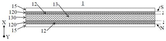
[0057] image 3 A schematic structural diagram of the optical film provided by the second embodiment of the present application is shown.

[0058] like image 3 As shown, the second embodiment of the present application also provides an optical film 1, which is similar in structure to the optical film 1 of the first embodiment, except that the magneto-optical medium layer 130 is sandwiched between two layers of between the magnetic layers 120 .

[0059] Specifically, the magnetic powder 12 and the light-transmitting substrate 11 are combined to form a layered magnetic layer 120 , the magneto-optical medium 13 and the light-transmitting substrate 11 are combined to form a magneto-optical medium layer 130 , and the magneto-optical medium layer 130 is sandwiched between two between the layered magnetic layers 120 . The magnetic powder of each layered magnetic layer 120 is magnetized in a magnetic field before being made into a layered structure, and the directions of the magne...

no. 3 example

[0068] Figure 4 A schematic structural diagram of the optical film provided by the third embodiment of the present application is shown.

[0069] like Figure 4 As shown, the third embodiment of the present application also provides an optical film 1 , which is similar in structure to the optical film 1 of the first embodiment, except that the light-transmitting substrate 11 , the magnetic powder 12 and the magneto-optical medium 13 is compounded to form a layered diaphragm, the magneto-optical medium 13 is a thin sheet structure, and the plane where the thin sheet structure is located is perpendicular to the magnetic field direction of the surface magnetic field.

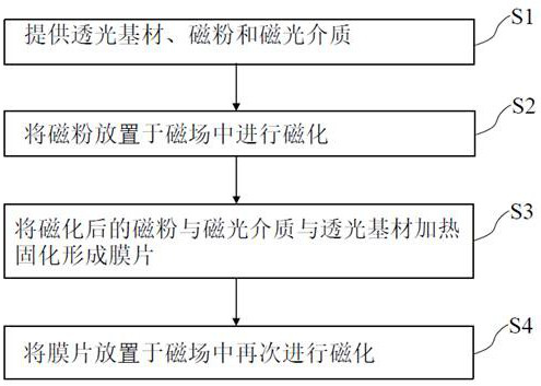
[0070] Specifically, a mixed powder is composed of silica aerogel, ultra-fine NdFeB magnetic powder, and magneto-optical medium powder (such as YIG, Ga-doped YIG, or CdMgTe crystal), and the mixed powder is placed in a magnetic field by vibration. The magnetic powder 12 is magnetized. After heating and curing t...


PUM


Abstract

The invention relates to an optical film, a preparation method thereof and a display device. The optical film comprises a light-transmitting base material and magnetic powder and a magneto-optical medium which are arranged in the light-transmitting base material, the magnetic powder is used for forming a surface magnetic field, and the magneto-optical medium is located in the surface magnetic field, so that the polarization direction of linearly polarized light rotates after the linearly polarized light penetrates through the magneto-optical medium. According to the optical film, the magnetic powder and the magneto-optical medium are arranged in the light-transmitting base material, the magnetic powder is used for forming the surface magnetic field, and the magneto-optical medium is located in the surface magnetic field, so that the polarization direction of linearly polarized light rotates after the linearly polarized light penetrates through the magneto-optical medium, and the optical film is applied to a backlight module of a display device. Natural light emitted by the backlight module can be converted into polarized light in the required polarization direction as much as possible, and the backlight utilization rate is increased.

Description

technical field [0001] The present application relates to the field of display technology, and in particular, to an optical film, a preparation method thereof, and a display device. Background technique [0002] A liquid crystal display device generally includes a liquid crystal display panel (Liquid Crystal Display, LCD for short) and a backlight module. The backlight module is disposed on the backlight side of the LCD to provide a light source for the LCD, so that the LCD displays images. [0003] The backlight penetration rate of LCD is often only about 5%. If the contrast ratio is increased, the penetration rate is often lower, so a brighter backlight is required. At present, the polarized brightness enhancement film (Dual Brightness Enhancement Films, DBEF for short) is used in LCD, so that the component of the natural light emitted by the backlight module that is in the same direction as the penetration axis of the polarizer under the LCD passes through, and the vertic...

Claims


Application Information

Patent Timeline
IPC IPC(8): G02F1/13357G02F1/09
CPCG02F1/13362G02F1/09G02F1/0136G02B6/0051G02B6/0053G02B6/0055G02B6/009G02B6/0028G02B6/0031G02B6/0088G02F1/133605G02F1/133608G02F1/133611G02F2201/50
Inventor 万业康报虹
Owner HKC CORP LTD
Why Eureka
Try Eureka