Device connector and manufacture method thereof

一种连接器、设备的技术,应用在其制造或模制领域,达到改进制造的效果

Active Publication Date: 2012-09-19
SUMITOMO WIRING SYST LTD
View PDF5 Cites 5 Cited by
  • Summary
  • Abstract
  • Description
  • Claims
  • Application Information

AI Technical Summary

Problems solved by technology

[0004] However, when the core is placed in the overmolding mold and the molding resin is injected into the overmolding mold, due to the influence of the injection pressure of the molding resin, the core rotates about the axis of the generatrix, and may Formation of secondary molded part in case of core displacement

Method used


Image

  • Device connector and manufacture method thereof
  • Device connector and manufacture method thereof
  • Device connector and manufacture method thereof

Examples


Embodiment Construction

[0061] refer to Figures 1 to 13 A specific embodiment of the present invention is described.

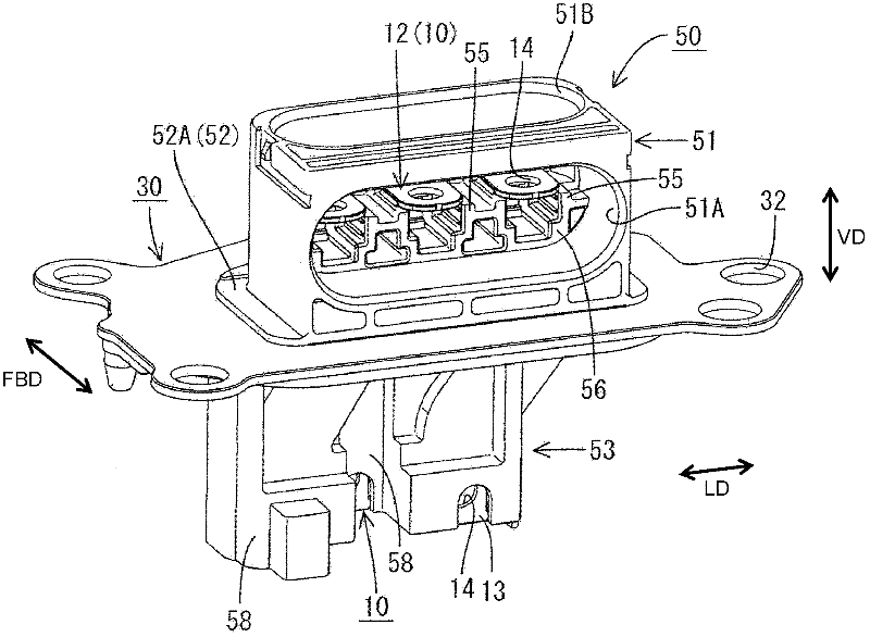
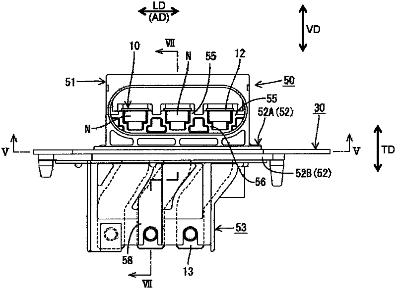
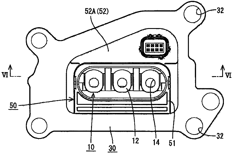
[0062] In this embodiment, shown as an example of a device connector is a terminal block that can be connected to a metal motor housing (not shown) in which the motor (as an example of a "device") is housed. in the metal motor housing. Such as figure 1 As shown, the terminal block includes: a metal plate 30 capable of being attached and fixed to a motor housing; a connector housing 50 integrally molded with the metal plate 30; and one or more (eg, three) conductive plates 10, particularly Accordingly, the conductive plate is held or accommodated in the connector housing 50 while penetrating through the metal plate 30 in the plate thickness direction TD. Note that the connector housing 50 specifically corresponds to a molded resin portion, and the one or more conductive plates 10 specifically correspond to conductors.

[0063] One or more ends (first ends) of the conductive plate...


PUM


Abstract

The invention relates to a device connector anda manufacture method thereof. An object of the present invention is to suppress displacements of cores and suppress the formation of voids and cracks in a molded resin portion. A terminal block in which a plurality of conductive plates (10) connected to device-side busbars provided in a motor are made integral by a connector housing (50) made of synthetic resin includes a plurality of cores (65) in which the conductive plates (10) are made integral to a primary molded portion (61); a metal plate (30) to be attached and fixed to a motor case; and a secondary molded portion (70) integrally forming the plurality of cores (65) held in contact side by side and the metal plate (30). A contact portion (66) is provided between a pair of adjacent cores (65, 65) and the pair of adjacent cores are held in contact via the contact portion.

Description

technical field [0001] The present invention relates to a device connector and to a method of manufacturing or molding the same. Background technique [0002] For example, in Japanese Unexamined Patent Publication No. 2009-32500, a device connector capable of being connected to a device such as a motor mounted in an electric vehicle or a hybrid vehicle has been disclosed. The device connector includes a plurality of metal bus bars for connecting device-side terminals provided in the device and wire-side terminals provided on power supply lines, and a molded resin portion covering the bus bars. [0003] Since insert molding is performed with a plurality of bus bars that are bent into complicated shapes and arranged side by side in the above-mentioned device connector, the mold release structure for the molded resin part becomes complicated and cannot be used in the molded resin part. Perform appropriate drilling on the Therefore, voids (small gaps) may be generated in the t...

Claims


Application Information

Patent Timeline
Patent Type & Authority Applications(China)
IPC IPC(8): H01R13/405H01R13/46H01R13/73H01R43/00H01R43/18
CPCB29C45/14065H01R13/405H01R43/24B29L2031/36B29C2045/14122B29C45/14639B29C45/33H01R43/18H01R2201/26H01R13/504B29C45/14467
Inventor 楯拓也松冈宏幸
Owner SUMITOMO WIRING SYST LTD
Why Eureka
Try Eureka