
Wear assembly for excavating equipment

一种挖掘设备、磨耗的技术,应用在移土机/挖土机、建筑等方向,能够解决增加挖泥作业时间和费用、不紧固等问题,达到减少阻力、降低功耗的效果

Active Publication Date: 2012-09-19
ESCO CORP
View PDF9 Cites 0 Cited by
  • Summary
  • Abstract
  • Description
  • Claims
  • Application Information

AI Technical Summary

Problems solved by technology

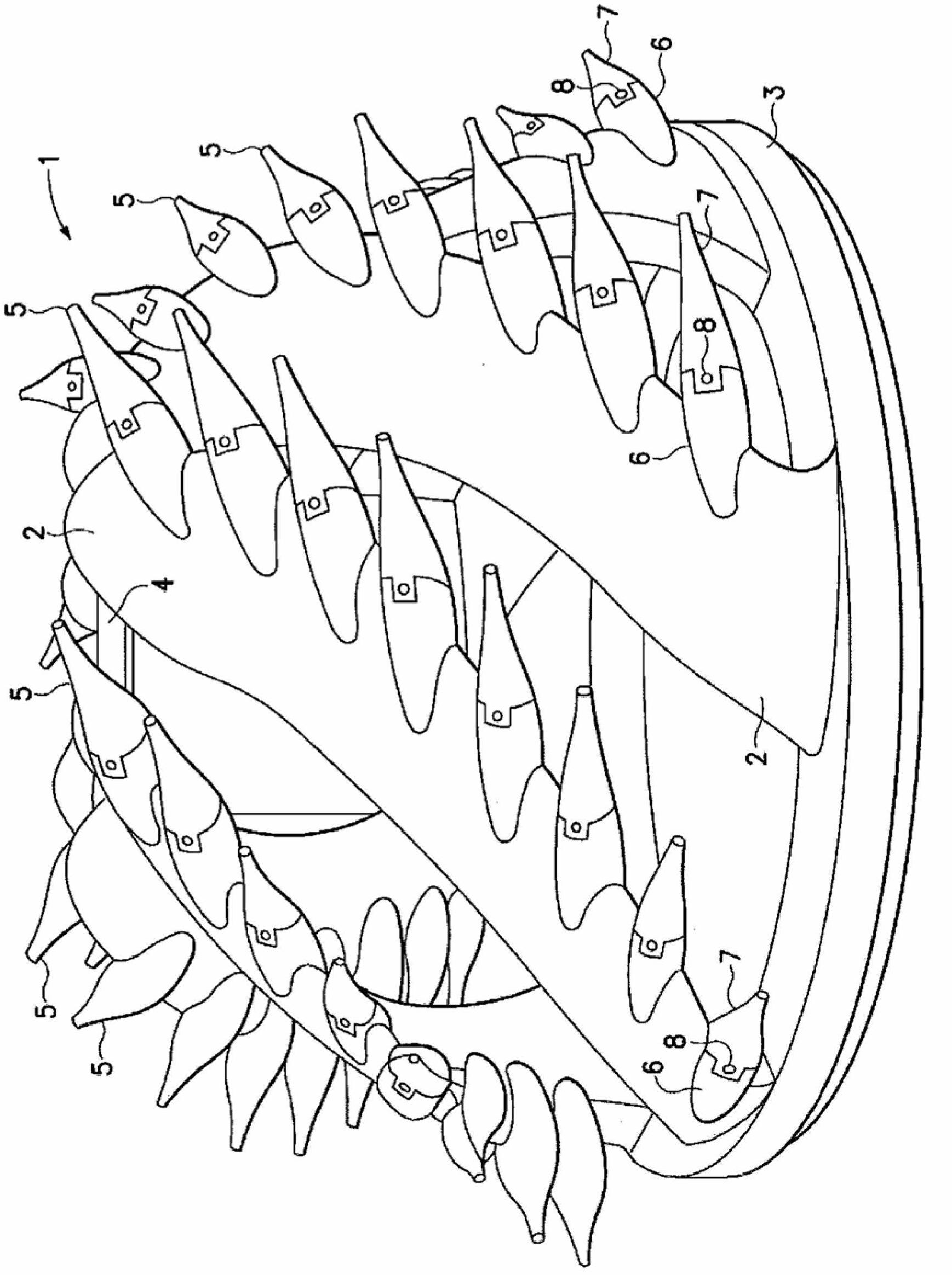
Unstable and loose engagement between the tips 7 and their bases 6 can lead to unwanted disengagement of the tips 7 from the base 6, which increases time and expense in dredging operations, for example due to lost parts, Downtime for replacement tips and more

Method used


Image

  • Wear assembly for excavating equipment
  • Wear assembly for excavating equipment
  • Wear assembly for excavating equipment

Examples


Embodiment Construction

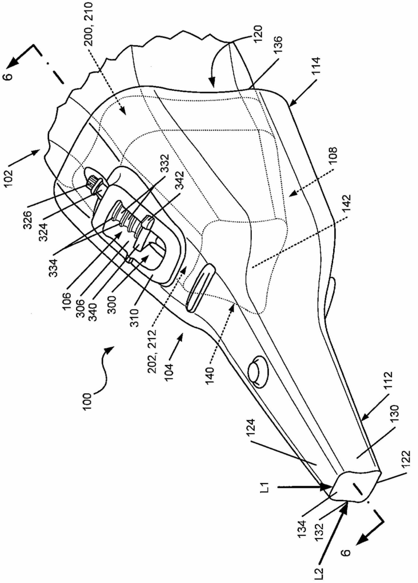
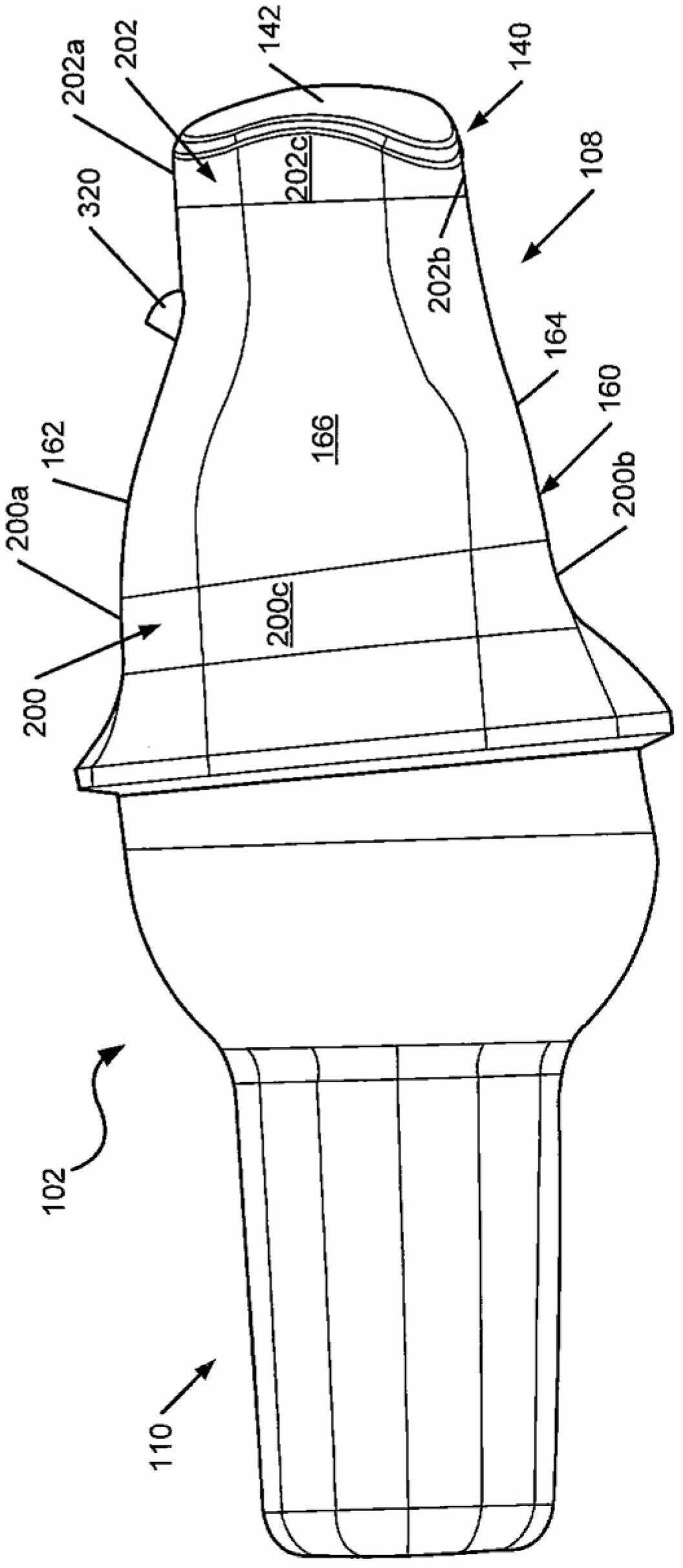
[0047] The following description and drawings disclose exemplary features of excavation equipment, including wear member structures for excavation equipment and structures for mounting the wear members according to examples of the present invention.

[0048] Aspects of the invention relate to wear assemblies 100 for excavation equipment that may be particularly well suited for dredging operations. In this application, the invention is mainly described in terms of dredging teeth adapted to be attached to a dredger cutter head. However, different aspects of the present invention may be used in conjunction with other types of wear assemblies (eg, pipe covers), and with other types of excavating equipment (eg, buckets for construction or mining equipment, etc.).

[0049] Assembly 100 and / or portions thereof are often described in relative terms such as "upper," "lower," "horizontal," "vertical," "front," and "rear," and the like. Such terms are not considered necessary and are me...


PUM


Abstract

Wear members for use in excavating include a socket having a front stabilizing end that includes a top surface, a bottom surface and side surfaces. At least one of these surfaces is formed with a transverse, inward projection and extends axially substantially parallel to the longitudinal axis of the socket. The socket may include surfaces that generally correspond to exterior surfaces of a nose on which it may be mounted and on which it may be connected to excavating equipment.

Description

[0001] relevant application data [0002] This application claims the benefit of priority to U.S. Provisional Patent Application No. 61 / 256,561, filed October 30, 2009, in the name of Christopher Snyder, entitled "Wear Assembly for Excavating Equipment," which is hereby incorporated by reference in its entirety . technical field [0003] The present invention relates to a wear assembly for securing a wear member to excavating equipment, such as a wear assembly adapted to be attached to and used on a dredger cutterhead. Background technique [0004] Dredger cutterheads are used to dredge submerged earth material, such as river beds. Typically, a dredger cutter head 1 comprises a number of arms 2 extending forward from a base ring 3 to a hub 4 ( FIG. 1 ). The arms 2 are spaced around the base ring 3 and form a wide spiral around the central axis of the cutter head 1 . Each arm 2 is provided with a series of spaced teeth 5 for digging into the ground. The tooth 5 consists o...

Claims


Application Information

Patent Timeline
Patent Type & Authority Applications(China)
IPC IPC(8): E02F9/28
CPCE02F9/2825E02F9/2858E02F9/2866E02F9/2833
Inventor C.D.斯奈德
Owner ESCO CORP
Learn More