
Electrically-assisted engine braking

An engine braking and generator technology, applied in engine control, engine components, combustion engines, etc., to solve problems such as battery degradation

Pending Publication Date: 2020-05-26
FORD GLOBAL TECH LLC
View PDF0 Cites 0 Cited by
  • Summary
  • Abstract
  • Description
  • Claims
  • Application Information

AI Technical Summary

Problems solved by technology

Also, the increase in pressure provided by the supercharger may not be regulated by adjusting the opening of the exhaust valve
Additionally, continuing to charge the battery when its state of charge (SOC) reaches 100% may cause battery degradation

Method used


Image

  • Electrically-assisted engine braking
  • Electrically-assisted engine braking
  • Electrically-assisted engine braking

Examples


Embodiment Construction

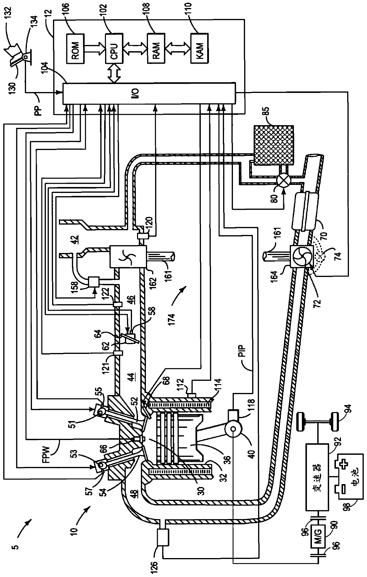
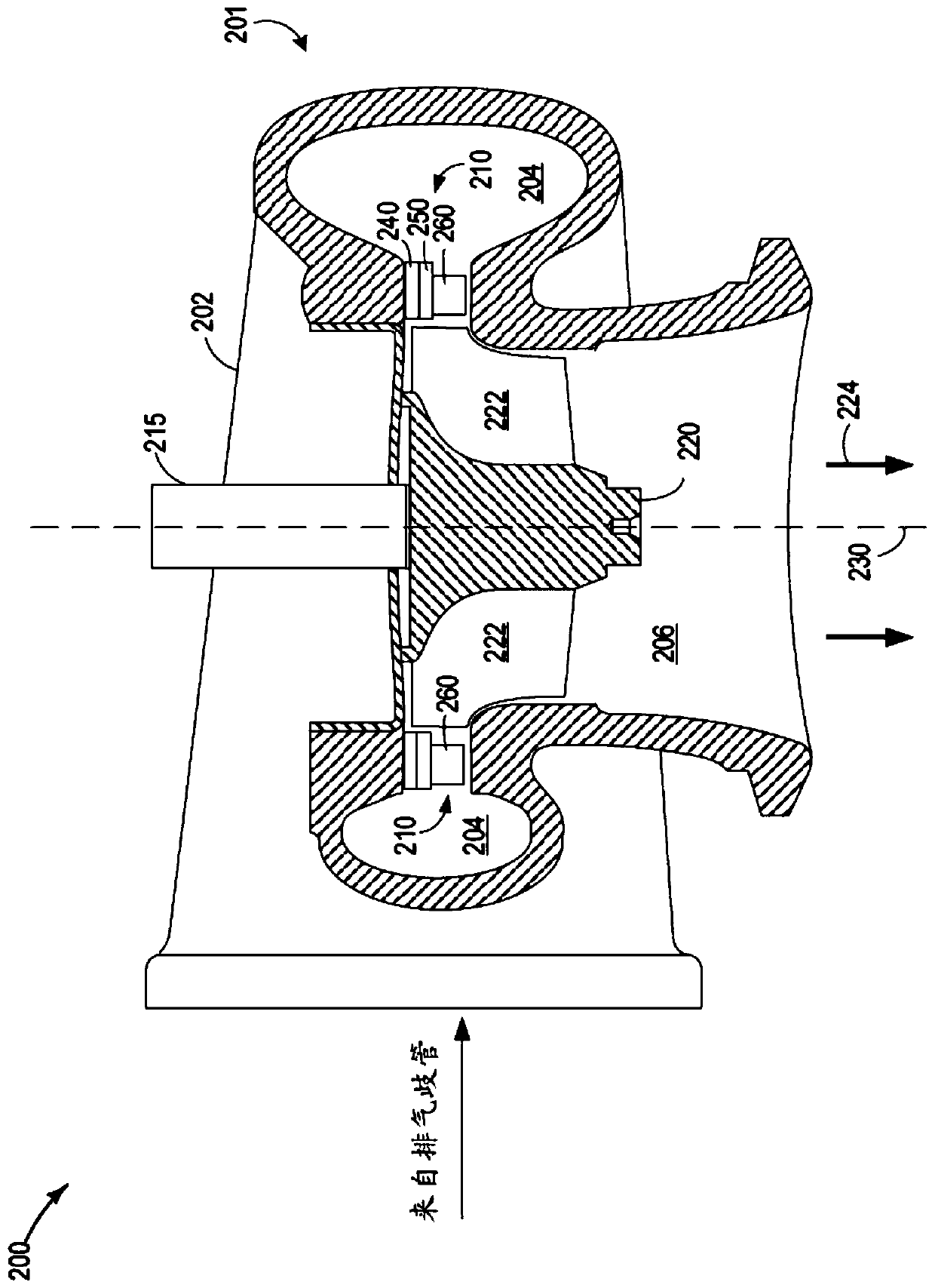
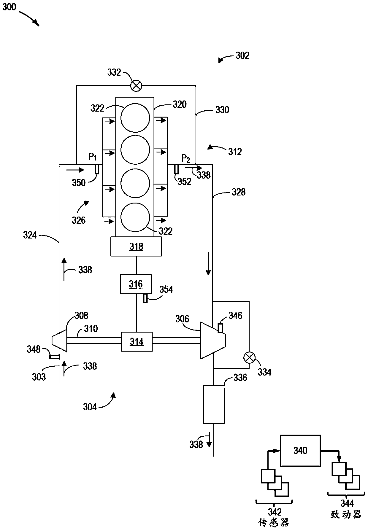
[0017] The following description relates to systems and methods for increasing engine braking power while maintaining use of regenerative braking. Exhaust braking can be used in diesel engines to use increased exhaust manifold pressure to counteract the engine's compression stroke and slow the engine down. Regenerative braking may be used in conjunction with exhaust braking to provide additional braking force while recovering braking energy to recharge the vehicle's electrical storage device. Therefore, the coordinated use of exhaust braking and regenerative braking may be particularly attractive for hybrid electric vehicles (HEVs), which include a traction battery to propel the HEV, thereby reducing the use of mechanical friction brakes and increasing the HEV's fuel consumption. economy. However, an upper bound on the braking torque provided by exhaust braking can be attributed to the intake air flow to the engine. This problem can be addressed by engine braking methods tha...


PUM


Abstract

Methods and systems are provided for electrically-assisted engine braking. A method and a system for electrically an assisted engine braking are provided. In one example, a method may include operating a turbocharger by an electric motor during engine braking to increase air flow to an engine intake. The enhanced air flow into the engine intake increases an exhaust manifold pressure, thus increased a braking force provided by engine braking.

Description

technical field [0001] The present description generally relates to methods and systems for engine braking in a vehicle. Background technique [0002] In diesel-powered and lean-burn supercharged gasoline-powered vehicles, the desired deceleration rate of the engine may not be achieved by releasing the accelerator pedal due to unrestricted airflow to the engine. Conversely, restrictions on airflow can depend on the flow capabilities of components directly in the flow path, including air cleaners, supercharging devices such as turbocharger compressors, intercoolers, intake manifolds, and in the cylinder head. port and intake valve openings. Without additional assistance, the slowing of the engine can rely solely on the mechanical brakes, making them susceptible to overheating and subject to frequent use, thus accelerating the degradation of the mechanical brakes. [0003] The deceleration of diesel engines can be assisted by fitting exhaust brakes to the vehicle. An exhaus...

Claims


Application Information

Patent Timeline
IPC IPC(8): F02B37/22F01D17/16F02D23/00F02D31/00F02D41/04F03G7/08
CPCF02D41/042F02D31/00F02D23/00F03G7/08F01D17/16F02B37/22B60K6/48B60K2006/4825B60W10/198B60W20/14B60W30/18127B60W2510/244Y02T10/12B60W30/18136B60W2710/0638F02D41/0007F02D41/0005F02D2250/24F02B37/24F02B37/18F02M26/05Y02T10/40Y02T10/62F16D61/00B60T1/10B60W10/06B60W20/15B60L2240/423B60K6/485B60W10/26
Inventor 胡良军德维什·乌帕德亚宋康
Owner FORD GLOBAL TECH LLC
Learn More