Ball mill

A bead mill and grinding chamber technology, applied in the field of grinding equipment, can solve the problems of low efficiency and small one-time grinding volume, and achieve the effect of high grinding efficiency and large grinding volume

Inactive Publication Date: 2014-04-16
苏州聚贝机械设计有限公司
View PDF9 Cites 0 Cited by
  • Summary
  • Abstract
  • Description
  • Claims
  • Application Information

AI Technical Summary

Problems solved by technology

[0002] The bead mill is a kind of equipment used for grinding, mainly including the rotor and the stator. The gap between the rotor and the stator constitutes the grinding chamber, and the material is fed into the grinding chamber for grinding. The main grinding principle of the bead mill is through the The grinding rods on the stator and the steel balls poured into the grinding chamber are realized. When the rotor rotates, the grinding rods on the rotor are driven to rotate. Under the joint action of the grinding rods and steel balls, the materials are simultaneously mixed, dispersed, kneaded, Physical effects such as rolling, friction and shearing, but the bead mill in the prior art is mainly composed of a rotor cylinder and a stator column located in the rotor cylinder, and the material is added between the inner wall of the rotor cylinder and the outer wall of the stator column. Grinding, so the amount of grinding at one time is small, and the efficiency is not high

Method used


Image

  • Ball mill

Examples


Embodiment

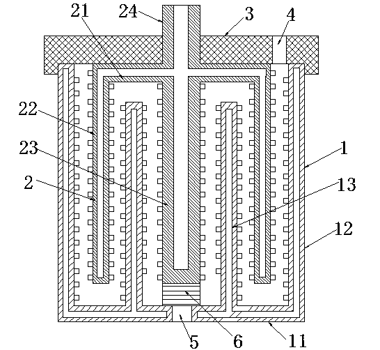
[0009] Embodiment: a bead mill, comprising a stator and a rotor, a grinding cavity is formed between the stator and the rotor, a plurality of grinding rods are arranged on the stator and the rotor, and a plurality of grinding rods are located in the grinding cavity, the stator It is a stator cylinder 1, and the stator cylinder is composed of a circular bottom surface 11, an outer ring cylinder wall 12 with a circular cross section and an inner cylinder wall 13 with a circular cross section. The wall is integrally formed upwards from the edge of the bottom surface, and the inner ring tube wall is integrally formed upwards from the middle of the bottom surface, and the bottom surface, the outer ring tube wall and the inner ring tube wall are coaxial, and the The rotor is a rotor cylinder 2, which consists of a circular top surface 21, a rotor cylinder wall 22 with a circular cross section, a central column 23 with a circular cross section and a connecting shaft with a circular cr...


PUM


Abstract

The invention discloses a ball mill which comprises a stator cylinder body consisting of a bottom surface, an outer-circle cylinder wall and an inner-circle cylinder wall and a rotor cylinder body consisting of a top surface, a rotor cylinder wall, a central post and a connecting shaft, wherein the rotor cylinder wall is arranged between the outer-circle cylinder wall and the inner-circle cylinder wall, the central post is arranged in the inner-circle cylinder wall, an outer-circle grinding cavity is formed between the outer-circle cylinder wall and the rotor cylinder wall, a middle-circle grinding cavity is formed between the rotor cylinder wall and the inner-circle cylinder wall, and an inner-circle grinding cavity is formed between the inner-circle cylinder wall and the central post, so that the ball mill disclosed by the invention is provided with three grinding cavities, and the material enters from a material inlet, and is sequentially ground by the outer-circle grinding cavity, the middle-circle grinding cavity and the inner-circle grinding cavity, screened by a screening device, and discharged outside a material outlet, therefore, compared with the ball mill which is provided with only one grinding cavity, the ball mill is higher in grinding quantity, and higher in grinding efficiency.

Description

technical field [0001] The invention belongs to the field of grinding equipment, in particular to a bead mill with large capacity and high efficiency. Background technique [0002] The bead mill is a kind of equipment used for grinding, mainly including the rotor and the stator. The gap between the rotor and the stator constitutes the grinding chamber, and the material is fed into the grinding chamber for grinding. The main grinding principle of the bead mill is through the The grinding rods on the stator and the steel balls poured into the grinding chamber are realized. When the rotor rotates, the grinding rods on the rotor are driven to rotate. Under the joint action of the grinding rods and steel balls, the materials are simultaneously mixed, dispersed, kneaded, Physical effects such as rolling, friction and shearing, but the bead mill in the prior art is mainly composed of a rotor cylinder and a stator column located in the rotor cylinder, and the material is added betwe...

Claims


Application Information

Patent Timeline
Patent Type & Authority Patents(China)
IPC IPC(8): B02C17/16B02C17/18
Inventor 周文荣
Owner 苏州聚贝机械设计有限公司
Why Eureka
Try Eureka