Motor rotor and IPM motor

A technology of motor rotor and motor stator, which is applied in the direction of electromechanical devices, electrical components, electric components, etc., and can solve the problems of complex process and high cost

Active Publication Date: 2021-11-12
BEIJING ZHONG KE SAN HUAN HI TECH
View PDF15 Cites 0 Cited by
  • Summary
  • Abstract
  • Description
  • Claims
  • Application Information

AI Technical Summary

Problems solved by technology

[0004] The purpose of the present disclosure is to provide a motor rotor and an IPM motor with the motor rotor, so as to solve the problems

Method used


Image

  • Motor rotor and IPM motor
  • Motor rotor and IPM motor
  • Motor rotor and IPM motor

Examples


Embodiment 1

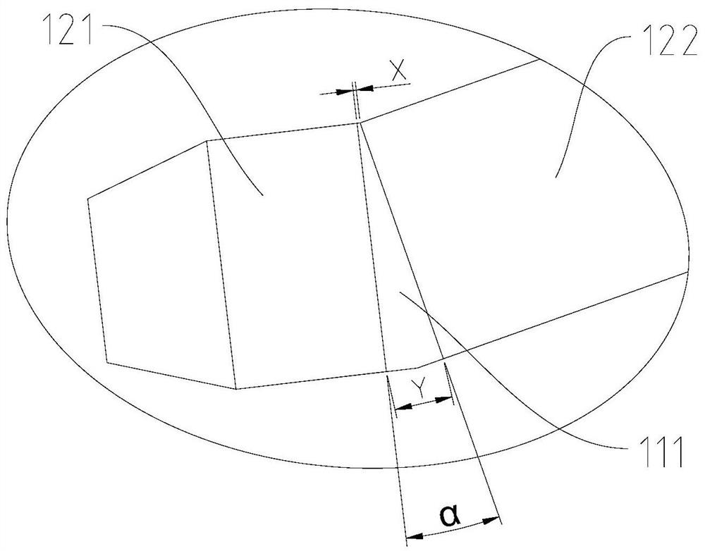
[0046] The length L2=22mm of the second magnet 122, the included angle α=0° between the adjacent surfaces of the first magnet 121 and the second magnet 122, the minimum between the adjacent surfaces of the first magnet 121 and the second magnet 122 Gap X=0.2 mm. Here, since the adjacent surfaces of the first magnet 121 and the second magnet 122 are parallel, the aforementioned minimum gap is also the maximum gap.

[0047] The length L1 of the first magnet 121 is 3 mm, 5 mm, 8 mm, and 11 mm, and the JMAG17.0 electromagnetic simulation calculation can be performed to obtain the total eddy current loss (ie, eddy loss) of the magnet 120, the output torque of the motor, and the first magnet 121 The temperature rise coefficient of the obtained table 1 below, temperature rise coefficient = (eddy loss 当前例 / volume 当前例 ) / (Eddy loss 对比例 / volume 对比例 ). Wherein, the percentage data in the table is with no gap between the first magnet 121 and the second magnet 122, and the situation (de...

Embodiment 2

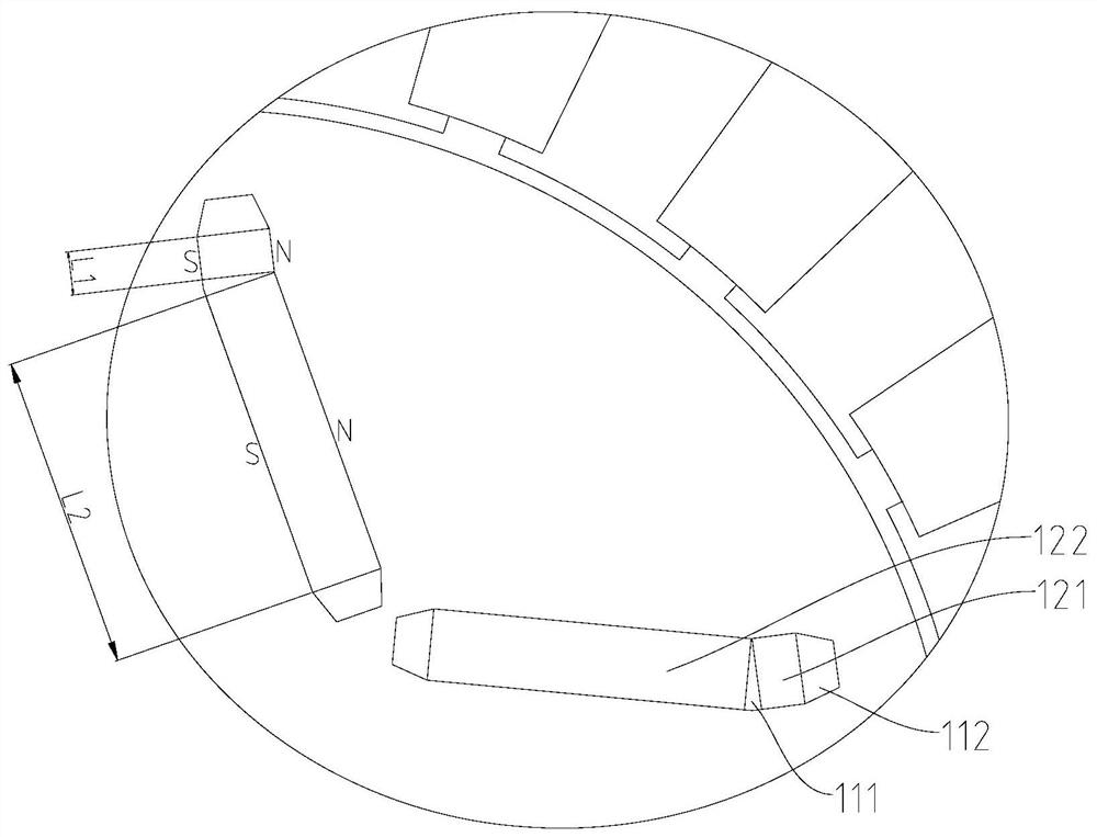
[0052] Since the eddy current increases with the increase of the motor speed, the scheme of embodiment 1 is adopted. When the length L1 of the first magnet 121 is preferably 3mm, in order to further explore the possibility of reducing the eddy current loss, the second embodiment changes the first The included angle between the adjacent surfaces of the first magnet 121 and the second magnet 122 is used for simulation experiments. Here, the length L2 of the second magnet 122 = 22 mm, the length L1 of the first magnet 121 = 3 mm, and the minimum gap X between adjacent surfaces of the first magnet 121 and the second magnet 122 = 0.2 mm.

[0053] The angle α between the adjacent surfaces of the first magnet 121 and the second magnet 122 is 0°, 2°, 8°, 10°, 15°, and 20° through computer simulation calculation, and the magnet 120 can be obtained. The total eddy current loss, the output torque of the motor and the temperature rise coefficient of the first magnet 121 are obtained in th...

Embodiment 3

[0058] The length L2 of the second magnet 122 is 22 mm, the length L1 of the first magnet 121 is 3 mm, and the angle α between adjacent surfaces of the first magnet 121 and the second magnet 122 is 15°.

[0059] Perform computer simulation calculations for different situations in which the minimum gap X between the first magnet 121 and the second magnet 122 is different values, and the eddy current loss, the output torque of the motor and the temperature rise coefficient of the first magnet 121 can be obtained to obtain the following table 3, wherein , the percentage data in the table is based on the situation that there is no gap between the first magnet 121 and the second magnet 122, and the sum of the lengths of the two is 25mm (the first magnet 121 and the second magnet 122 can be in close contact or as a whole) as a reference .

[0060] Table 3 (embodiment three)

[0061] X(mm) Eddy current loss (%) Output torque (%) Temperature rise coefficient of the fi...


PUM

PropertyMeasurementUnit
Coercivityaaaaaaaaaa
Angleaaaaaaaaaa

Abstract

The present disclosure relates to a motor rotor and an IPM motor. The motor rotor comprises an iron core (110), mounting grooves (111) recessed from the end face of the iron core (110) and magnets (120) embedded in the mounting groove, wherein the mounting groove extends in a direction from the middle portion of the iron core to an outer peripheral surface, the magnets comprise first magnets and second magnets which are arranged at intervals in the extending directions of the mounting grooves, the magnetizing direction of the first magnets is perpendicular to the extending directions of the mounting grooves, the first magnets are fixed to the radial outer sides of the second magnets, and the coercive force of the first magnets is larger than that of the second magnets. According to the invention, the first magnets and the second magnets are arranged at intervals, the mode that the first magnets and the second magnets are combined into a whole through a complex bonding technology with higher cost does not need to be considered, and the problem that the two kinds of magnets combined into a whole are separated due to the fact that a binding agent is softened due to temperature rise in the working process is fundamentally eradicated.

Description

technical field [0001] The present disclosure relates to the field of motor technology, in particular, to a motor rotor and an IPM motor. Background technique [0002] IPM (Interior Permanent Magnet) motor refers to the built-in permanent magnet motor in which the magnets are embedded in the silicon steel core of the motor rotor. With the development of motor technology, various modern drive motors including new energy vehicles, in order to increase the energy density of the motor (that is, the power output per unit motor volume), the speed of the motor must be increased. The higher the rotational speed, the higher the frequency of the magnetic field that the magnet is subjected to from the stator armature. This alternating magnetic field acting on the magnet will cause eddy currents to form in the magnet. On the one hand, the eddy current causes the temperature of the magnet to increase, the magnetism to decrease, and even to lose the magnetism; on the other hand, because ...

Claims


Application Information

Patent Timeline
IPC IPC(8): H02K1/27H02K1/02
CPCH02K1/274H02K1/02H02K2213/03H02K1/2766H01F1/0577H01F1/0536H01F1/057
Inventor 何叶青王进东史学伟白山饶晓雷胡伯平
Owner BEIJING ZHONG KE SAN HUAN HI TECH
Why Eureka
Try Eureka