Machine head component of tubing thread forming machine

A technology of thread forming machine and forming parts, which is applied in the direction of threaded products, other household appliances, household appliances, etc., which can solve the problems of pipe body stress concentration and fracture, and achieve improved production efficiency, high processing accuracy, and thread forming depth. adjustable effect

Active Publication Date: 2012-09-26
锦州秀亭制管有限公司
View PDF4 Cites 3 Cited by
  • Summary
  • Abstract
  • Description
  • Claims
  • Application Information

AI Technical Summary

Problems solved by technology

[0003] The technical problem to be solved by the present invention is to provide a pipe thread forming machine head assembly. Compared with the existing pipe thread forming machine head assembly, it has high production efficiency, high processing precision, and diversified production products. The problem of excessive stress concentration and easy fracture

Method used


Image

  • Machine head component of tubing thread forming machine
  • Machine head component of tubing thread forming machine
  • Machine head component of tubing thread forming machine

Examples


Embodiment 1

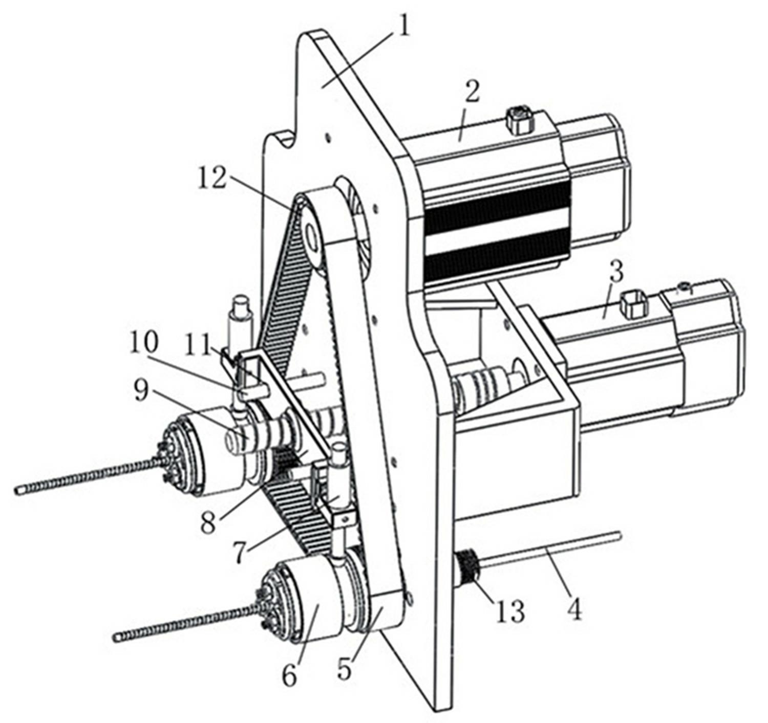
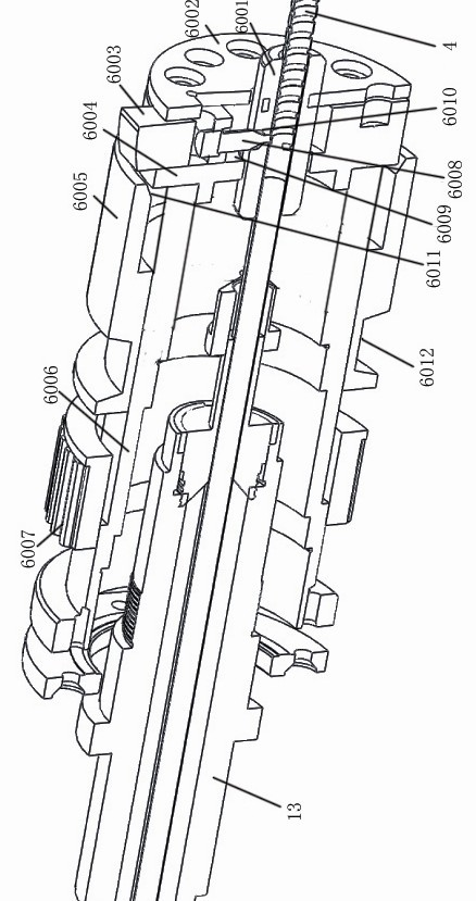
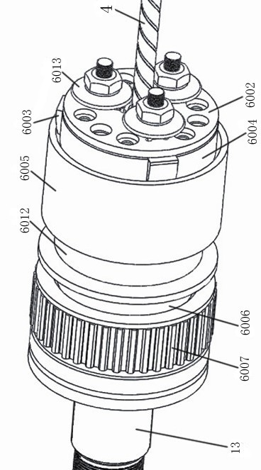
[0027] Such as figure 1 , figure 2 As shown, the head assembly of the pipe thread forming machine includes a bracket 1, two molding dies 6 arranged on the bracket 1 and their transmission devices. The molding die 6 includes a molding sleeve 6001 and a support frame 6004 set on the molding sleeve 6001. 1. Thread forming parts, the bracket 1 is respectively provided with hollow shafts 13 for installing two molding dies 6, the front surface of the support frame 6004 is provided with a stopper 6002, and the entrance end of the stopper 6002 corresponding to the forming sleeve 6001 is provided with Hollow hole, the rear end of the support frame 6004 is fixedly connected with a rotating support sleeve 6006, the rotating support sleeve 6006 is set on the hollow shaft 13 and rotates around it, the axis line of the hollow shaft 13 and the axis line of the forming sleeve 6001, and the support frame 6004 The axial lines of the hollow shaft 13 are coincident, and the aperture of the thro...

Embodiment 2

[0032] Such as Figure 3-Figure 5 As shown, in the present embodiment, three radial chute 6009 are evenly provided on the peripheral surface of the support frame 6004, and the wedge-shaped slider 6003 whose top surface is higher than the chute 6009 and slides along the chute 6009 is arranged in the chute 6009, and the thread forming part is The three rollers 6013 are symmetrically arranged on the front end of the block 6002 at a position corresponding to the slider 6003 at an angle of 120°, and the roller shafts 6016 of the three rollers 6013 respectively pass through the block 6002 and are connected to the side of the corresponding slider 6003. The sheet 6002 is provided with radial elongated holes 6015 corresponding to the roller shaft 6016 . Others are the same as embodiment 1.

[0033]The servo motor Ⅱ3 starts first, the lead screw 9 rotates, the lead screw 9 drives the shift fork frame 8 and the two shift forks 7 on it to slide forward, the shift fork 7 pushes the corres...

Embodiment 3

[0035] Such as Figure 6 As shown, in the present embodiment, three radial chute 6009 are uniformly provided on the peripheral surface of the support frame 6004, and the wedge-shaped slider 6003 whose top surface is higher than the chute 6009 and slides along the chute 6009 is arranged in the chute 6009. A roller 6013 and two bearings 6014 that are evenly distributed on the front end of the blocking piece 6002 along the circumferential direction corresponding to the position of the slider 6003 are formed. The shafts are respectively connected to the side of the corresponding slider 6003 through the blocking piece 6002, and the blocking piece 6002 is provided with a radial elongated hole 6015 corresponding to the roller shaft 6016 and the shaft of the bearing. Others are the same as embodiment 1.

[0036] The servo motor Ⅱ3 starts first, the lead screw 9 rotates, the lead screw 9 drives the shift fork frame 8 and the two shift forks 7 on it to slide forward, the shift fork 7 p...


PUM


Abstract

The invention discloses a machine head component of a tubing thread forming machine. The machine head component comprises a support, forming moulds and transmission devices of the forming moulds. Each forming mould comprises a forming sleeve, and a support frame and a thread forming member which are sleeved on the forming sleeve, and the machine head component of the tubing thread forming machine is characterized that a plurality of forming moulds are arranged on the support; a block plate is arranged on the front end surface of the support frame; a hollow hole is arranged in the block plate corresponding to the inlet end of the forming sleeve; one or three radial sliding grooves are uniformly arranged on the circumference of the support frame; a wedge slider of which the top surface is high above the sliding grooves is arranged in the sliding grooves, and the wedge slider slides along the sliding grooves; the thread forming member is connected integrally with the slider; a rotary support sleeve is connected to the rear end of the support frame; and a movable jacket is arranged on the outer side of the rotary support sleeve. Compared with the machine head component of the conventional tubing thread forming machine, the machine head component provided by the invention is high in production efficiency and machining accuracy, and is variable in production product; and moreover, the problems that the stress of the tube is excessively concentrated and the tube is easy to fracture are solved.

Description

technical field [0001] The invention relates to a pipe thread forming machine, in particular to a head assembly of a pipe thread forming machine. Background technique [0002] The head assembly of the existing pipe thread forming machine generally includes a bracket, a molding die and a transmission device arranged on the bracket, so only one pipe production line is formed, and the production efficiency is low. The forming mold includes a forming sleeve, a support frame set on the forming sleeve, and a threaded part on the support frame. The threaded part defines conditions such as the pipe diameter and the depth of the thread on the pipe, so the structural form of the threaded pipe has limitations. Not suitable for diverse market demands. In addition, during processing, the pipe rotates, the forming die moves along the length of the pipe, and the stylus forms threads on the pipe wall. Such a processing method is unfavorable for cold-worked pipes. Under the same torsional ...

Claims


Application Information

Patent Timeline
Patent Type & Authority Applications(China)
IPC IPC(8): B21H3/04B21H3/06
Inventor 郭淼李绮霞李冰冰杨少先
Owner 锦州秀亭制管有限公司
Why Eureka
Try Eureka