The base of the automatic beveling machine

A beveling machine and automatic technology, applied in the field of beveling machines, can solve the problems that automatic processing cannot be realized, and the height direction of the beveling machine cannot be automatically adjusted.

Active Publication Date: 2016-01-06
YANGZHOU HONGCHENG MACHINERY
View PDF10 Cites 0 Cited by
  • Summary
  • Abstract
  • Description
  • Claims
  • Application Information

AI Technical Summary

Problems solved by technology

At present, there are hand-held flame cutting methods for steel plate cutting and bevel processing of workpieces before welding on the market, as well as other cutting equip

Method used


Image

  • The base of the automatic beveling machine

Examples


Embodiment Construction

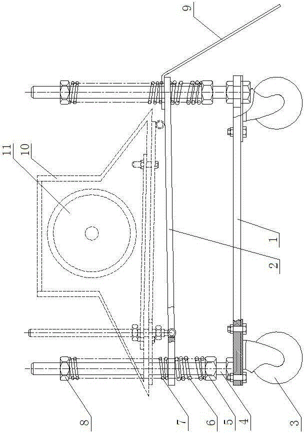
[0009] Such as figure 1 As shown, the base of the automatic beveling machine includes a roller bracket 1, four rollers 3 are connected to the bottom of the roller bracket 1, four bolts 4 are placed on the roller bracket 1, and a backing plate 2 and a backing plate 2 are arranged above the roller bracket 1 One side is connected with the screen plate 9, and each bolt 4 is respectively inserted on the backing plate 2, and each bolt 4 is threaded to connect the lower nut 5 and the upper nut 8 respectively, and each lower nut 5 is respectively arranged on the backing plate 2 and the roller Between the brackets 1 , each upper nut 8 is respectively arranged above the backing plate 2 . Thick springs 6 and thin springs 7 are respectively arranged on each bolt 4, each thick spring 6 is respectively arranged between the backing plate 2 and the corresponding lower nut 5, and each thin spring 7 is respectively arranged between the backing plate 2 and the corresponding upper nut 8 between....


PUM


Abstract

The invention relates to a bevelling machine which is used for steel plate cutting and bevel processing of a workpiece before welding, and particularly relates to a structure of a base of the bevelling machine. The base comprises a roller bracket, wherein four rollers are connected below the roller bracket; four bolts are arranged on the roller bracket in a penetrating way; a padding plate is arranged at the upper part of the roller bracket; each bolt is arranged on the padding plate in a penetrating way and is in threaded connection with an upper nut and a lower nut; each lower nut is arranged between the padding plate and the roller bracket; each upper nut is arranged over the padding plate; a thick spring and a thin spring are respectively arranged on each bolt; each thick spring is arranged between the padding plate and the lower nut corresponding to the thick spring; and each thin spring is arranged between the padding plate and the upper nut corresponding to the thin spring. When in operation, the bevelling machine is mounted on the base, and the rollers below the base roll forwards under the action of gravity of the bevelling machine, so that automatic feed is realized without being influenced by length and weight of the plate; and elasticity of the springs can allow the bevelling machine to be automatically adjusted up and down.

Description

technical field [0001] The invention relates to a beveling machine, which is used for steel plate cutting and beveling processing of workpieces before welding, in particular to the structure of the base of the beveling machine. Background technique [0002] When the workpiece is welded, in order to ensure the welding quality, it is necessary to open a bevel at the weld to increase the contact area of ​​the weld. At present, there are hand-held flame cutting methods for steel plate cutting and bevel processing of workpieces before welding on the market, as well as other cutting equipment such as edge planers and planers. Automatic processing cannot be realized, and the height direction of the beveling machine cannot be automatically adjusted up and down. Contents of the invention [0003] The purpose of the present invention is to overcome the deficiencies of the prior art, and provide a base of an automatic beveling machine, on which the beveling machine is connected or p...

Claims


Application Information

Patent Timeline
IPC IPC(8): B23Q1/25
Inventor 殷广富刘安福
Owner YANGZHOU HONGCHENG MACHINERY
Why Eureka
Try Eureka