Novel swirl chamber for internal combustion engine

An internal combustion engine and combustion chamber technology, which is applied in the field of swirl combustion chambers of internal combustion engines, can solve the problem of high fuel consumption of internal combustion engines, and achieve the effects of complete gas mixture, fuel consumption reduction and emission control.

Inactive Publication Date: 2012-09-26
慈溪三环柴油机有限公司
View PDF7 Cites 12 Cited by
  • Summary
  • Abstract
  • Description
  • Claims
  • Application Information

AI Technical Summary

Problems solved by technology

The connecting channel (main injection hole) between the traditional vortex chamber and the main combustion chamber is a single channel (single injection hole).

Method used


Image

  • Novel swirl chamber for internal combustion engine
  • Novel swirl chamber for internal combustion engine
  • Novel swirl chamber for internal combustion engine

Examples


Embodiment Construction

[0018] The present invention will be further described in detail below with reference to the drawings and specific embodiments.

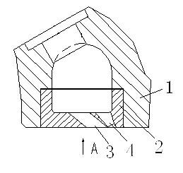
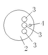
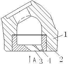
[0019] Reference figure 1 , figure 2 , A new type of internal combustion engine vortex combustion chamber, composed of a vortex chamber upper body 1 and a vortex chamber lower body 2. The vortex chamber lower body 2 is provided with three or two connecting channels 3, the vortex chamber through the connection The passage 3 communicates with the main combustion chamber. In this embodiment, there are three connecting channels 3, and the three connecting channels 3 are arranged in a row. Among the three connecting channels, the two connecting channels on both sides are symmetrical about the center line of the middle connecting channel. The angle between the centerline of the longitudinal section of the connecting channel 3 and the vertical centerline of the insert is 20o~70o. In this embodiment, it is 50°. Of course, it can also be 30°, 40°, etc., withi...


PUM


Abstract

A novel swirl chamber for an internal combustion engine comprises an upper swirl chamber body and a lower swirl chamber body, wherein three or two connecting passages are arranged on the lower swirl chamber body; and the novel swirl chamber is communicated with a main combustion chamber through the connecting passages. Through the adoption of the novel swirl chamber, the mixing of fuel gases is more complete, so as to achieve the purposes of controlling the emission of the internal combustion engine and reducing oil consumption.

Description

Technical field [0001] The invention relates to a vortex combustion chamber of an internal combustion engine. Background technique [0002] Internal combustion engines (diesel engines, gasoline engines and other gas engines) are the main power machinery in my country, and their combustion chambers have direct injection and non-direct injection (vortex chamber, pre-combustion chamber, etc.). Among them, the swirl chamber diesel engine occupies an important position in my country's national economy. As the power of automobiles, tractors, agricultural water pumps, harvesters, small construction machinery, small ships, etc., it is widely used in various industries such as transportation, agriculture, and industry, with an annual output of nearly 800 Ten thousand units are an obvious feature and advantage of the development of my country's internal combustion engine. [0003] In order to meet the strict requirements of emission regulations, some new trends have emerged in the research a...

Claims


Application Information

Patent Timeline
Patent Type & Authority Applications(China)
IPC IPC(8): F02B23/00
CPCY02T10/125Y02T10/12
Inventor 袁宜程陈公一蒋世晓韩行裘海波潘农科罗玉珍
Owner 慈溪三环柴油机有限公司
Why Eureka
Try Eureka