Device for light spot capture

A technology of light spot and light-shielding body, which is applied in the laser field and can solve problems such as affecting the quality of the beam and inconvenient operation

Inactive Publication Date: 2012-09-26
BEIJING GK LASER TECH
View PDF4 Cites 2 Cited by
  • Summary
  • Abstract
  • Description
  • Claims
  • Application Information

AI Technical Summary

Problems solved by technology

[0003] 1. After the spot passes through the aperture, there will be modulation inside, which affects the beam quality (such as figure 2 shown)
[0004] 2. If you want to adjust the shape and size of the aperture, you have to replace the aperture with a new one, which is very inconvenient to operate

Method used


Image

  • Device for light spot capture
  • Device for light spot capture
  • Device for light spot capture

Examples


Embodiment Construction

[0027] The present invention will be further described below in conjunction with the accompanying drawings and specific embodiments.

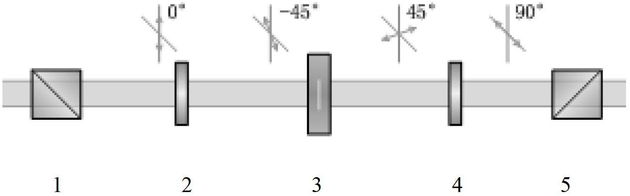
[0028] image 3 shows the optical path of the device for intercepting light spots according to an embodiment of the present invention, refer to image 3 , the device for intercepting the spot includes a polarization beam splitter prism 1 (Polarization Cube Beamsplitter, abbreviated as PBS), a left-handed 45° rotor 2, a liquid crystal spatial light modulator 3, a right-handed 45° rotor 4, and a polarization beam splitter arranged in sequence along the optical path. Prism 5.

[0029] In this embodiment, the first PBS acts as a polarizer (it is easy to understand that the PBS can also be replaced by a polarizer), which makes the polarization state of the light level. The left-handed 45° rotor rotates the light with a horizontal polarization state by 45° to the left, so that the polarization state of the light is 45° to the long axis of the liqui...


PUM


Abstract

The invention provides a device for light spot capture, which includes a light-shading body, wherein a light transmitting window is arranged in the light-shading body; transition zones are arranged at the edges of the light transmitting window; and the light transmission of the transition zones is gradually changed from full transmission to light-proof condition. The invention further provides a corresponding method for light spot capture. Compared with the prior art, the interior modulation of light spots can be avoided.

Description

technical field [0001] The invention relates to the field of laser technology, in particular, the invention relates to a device and method for intercepting light spots. Background technique [0002] In the prior art, a diaphragm is generally used in the laser light path to intercept the light spot, so as to limit the shape of the light spot propagating in the subsequent light path. Existing diaphragms are generally made of metal materials, and typical diaphragm structures are as follows: figure 1 As shown, the shape of the small hole is determined according to the needs, such as rectangle or circle. However, when the existing aperture is used to intercept the light spot, there are the following disadvantages: [0003] 1. After the spot passes through the aperture, there will be modulation inside, which affects the beam quality (such as figure 2 shown). [0004] 2. If you want to adjust the shape and size of the aperture, you have to replace the aperture with a new one, ...

Claims


Application Information

Patent Timeline
Patent Type & Authority Applications(China)
IPC IPC(8): G02F1/133G02B27/09
Inventor 邱基斯樊仲维唐熊忻
Owner BEIJING GK LASER TECH
Why Eureka
Try Eureka