
Special electric soldering iron device for disassembling electronic components

A technology of electronic components and electric soldering irons, which is applied in the direction of soldering irons, soldering positions, metal processing equipment, etc., can solve problems such as troublesome disassembly, affecting circuit reliability, and damaging solder pads of electronic components, so as to achieve easy identification and improve eye-catching , the effect of prolonging the service life

Pending Publication Date: 2020-11-27
750 TEST SITE OF CHINA SHIPBUILDING IND CORP
View PDF0 Cites 0 Cited by
  • Summary
  • Abstract
  • Description
  • Claims
  • Application Information

AI Technical Summary

Problems solved by technology

Conventional soldering irons are used to disassemble electronic components. When the components have many pins, disassembly will be very troublesome, especially for integrated circuits with multiple pins. Electrical engineers often have to work very hard to remove a component with many pins. Moreover, during the disassembly process, electronic components and pads on the circuit board are often damaged, which affects the reliability of the circuit.

Method used


Image

  • Special electric soldering iron device for disassembling electronic components
  • Special electric soldering iron device for disassembling electronic components
  • Special electric soldering iron device for disassembling electronic components

Examples


Embodiment 1

[0065] Such as Figure 9 As shown, to remove the electronic components 8 to be disassembled, only one of the four sets of heating unit assemblies 6 can be used. Only keep the group of heating unit components 6 without lifting them up, and adjust the number of soldering iron tips 61 on the group of heating unit components 6 to suit the overall size of the 8 pins of the electronic components to be disassembled. Power on the device, keep the power switches corresponding to the remaining three groups of heating unit components 6 off, turn on the power switch of the selected heating unit component 6, and disassemble the electronic components 8 to be disassembled after the temperature rises to the required temperature.

[0066] Finally, as time goes by, after the present invention is used, ensure that the four power switches are in the off state, unplug the plug, and after the electric soldering iron device cools down, it is cleaned up, and finally it is put into the storage room fo...

Embodiment 2

[0068] Such as Figure 10 As shown, to remove the electronic components 8 to be disassembled, only two groups of the four groups of heating unit assemblies 6 need to be used, that is, two groups of heating unit assemblies 6 facing left and right or two groups of heating unit assemblies 6 facing up and down, so as to use Two sets of heating unit assemblies 6 facing up and down are taken as an example. When in use, the two sets of heating unit assemblies 6 facing left and right are lifted by the corresponding adjustment connecting rod 4, and only the two sets of heating unit assemblies 6 facing up and down are kept. According to the overall size of the pins of the electronic components 8 to be disassembled, adjust the distance between the upper and lower relative two sets of heating unit assemblies 6 and the number of soldering iron tips. The corresponding power switches, the power switches connected to the two groups of heating unit assemblies 6 facing each other on the left an...

Embodiment 3

[0071] Such as Figure 11 As shown, removing the electronic components 8 to be disassembled needs to use four sets of heating unit assemblies 6 at the same time. The distance between the group of heating unit components 6 and the two groups of heating unit components 6 facing up and down and the number of soldering iron tips are consistent with the overall size of the 8 pins of the electronic components to be disassembled. After the adjustment and comparison are completed, power on the electric soldering iron device , turn on the power switches corresponding to the four groups of heating unit components 6, and disassemble the electronic components 8 to be disassembled after the temperature rises to the required temperature.

[0072] Finally, as time goes by, after the present invention is used, ensure that the four power switches are in the off state, unplug the plug, and after the electric soldering iron device cools down, it is cleaned up, and finally it is put into the stor...


PUM


Abstract

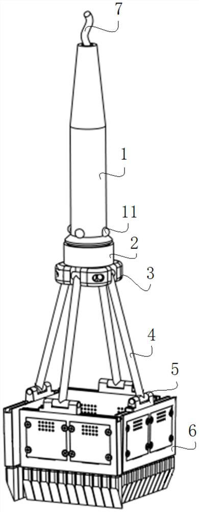
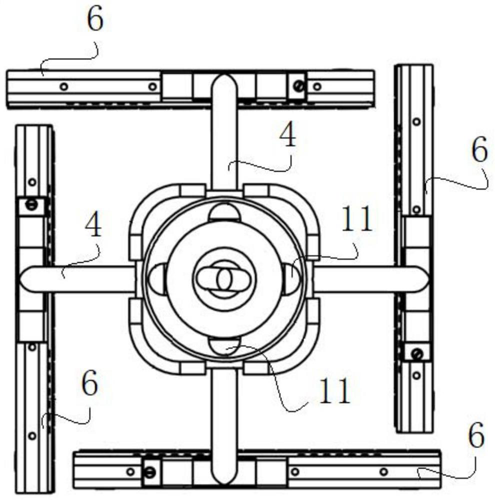
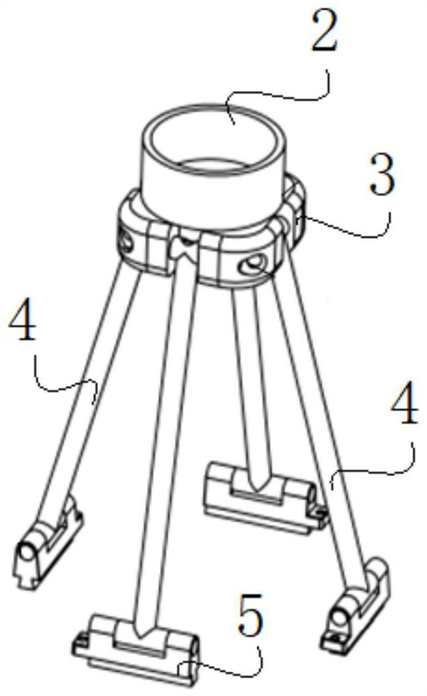
The invention discloses a special electric soldering iron device for disassembling electronic components. The special electric soldering iron device comprises a handle, an adjusting mounting seat, a damping adjusting frame, adjusting connecting rods, damping torque hinge sliding blocks, heating unit assemblies and a power line; a plurality of power switches are mounted on the handle, and the lowerend of the handle is in threaded connection with the adjusting mounting seat; the outer wall of the lower end of the adjusting mounting seat is connected with the damping adjusting frame, and the multiple adjusting connecting rods are mounted on the damping adjusting frame; the damping torque hinge sliding blocks are mounted at the other ends of the adjusting connecting rods; the heating unit assemblies are movably mounted at the lower ends of the damping torque hinge sliding blocks, and a plurality of soldering bits are detachably mounted at the lower ends of the heating unit assemblies, wherein positioning holes are formed in the damping torque hinge sliding blocks; and the power line is electrically connected with the power switches and the heating unit assemblies. The special electricsoldering iron device can be adjusted and used according to shapes and sizes of the different components to quickly and completely disassemble the components at a time, thus the disassembly efficiency is improved, and the reliability of the components and circuits can be guaranteed better.

Description

technical field [0001] The invention relates to an electric soldering iron device, in particular to a special electric soldering iron device for disassembling electronic components. Background technique [0002] Soldering iron is one of the necessary tools in the electronics industry. It is mainly used for welding components and wires. According to the mechanical structure, it can be divided into internal heating type electric soldering iron and external heating type electric soldering iron. When electrical engineers maintain, repair, and debug electrical appliances, they often need to maintain, repair, and debug the circuit board and the components on the circuit board, and disassemble the components when necessary. Conventional soldering irons are used to disassemble electronic components. When the components have many pins, disassembly will be very troublesome, especially for integrated circuits with multiple pins. Electrical engineers often have to work very hard to remo...

Claims


Application Information

Patent Timeline
Patent Type & Authority Applications(China)
IPC IPC(8): B23K3/03B23K1/018
CPCB23K3/03B23K1/018B23K3/025
Inventor 单江陶旭
Owner 750 TEST SITE OF CHINA SHIPBUILDING IND CORP
Learn More