
Method for realizing synchronization of carrier and sampling clock, and user site device

A sampling clock synchronization and sampling clock technology, which is applied to the synchronization device, shaping network in the transmitter/receiver, electrical components, etc. Multi-user synchronization requirements and other issues to achieve the effect of eliminating multiple access interference

Active Publication Date: 2012-09-26
新岸线(北京)科技集团有限公司
View PDF7 Cites 33 Cited by
  • Summary
  • Abstract
  • Description
  • Claims
  • Application Information

AI Technical Summary

Problems solved by technology

The two-way communication of the WLAN system is synchronized through the preamble. Although this synchronization method is simple, it is inefficient and cannot meet the needs of simultaneous communication of multiple users. On the one hand, no matter how long the data packet needs to carry the preamble, it will take up time resources; On the one hand, the CSMA / CA access method itself does not support simultaneous access by multiple users, so it does not meet the synchronization requirements for simultaneous communication of multiple users
The synchronization methods of mobile WiMAX and LTE systems can be used for reference, but the uplink synchronization of the two requires closed-loop control, which has high requirements for synchronization; in addition, mobile terminals and base stations use high-cost carrier crystal oscillators to deal with sampling clock synchronization issues, which are not suitable for low-cost WLAN device

Method used


Image

  • Method for realizing synchronization of carrier and sampling clock, and user site device
  • Method for realizing synchronization of carrier and sampling clock, and user site device
  • Method for realizing synchronization of carrier and sampling clock, and user site device

Examples


Embodiment Construction

[0027] Those skilled in the art know that the purpose of carrier frequency synchronization is to correct the frequency offset due to the inconsistency between the frequency oscillators of the transmitter and the receiver and the Doppler effect. The receiver based on OFDM technology must perform FFT transformation before The frequency offset is estimated and compensated to reduce the damage to the orthogonality between the subcarriers by the frequency offset. Carrier frequency synchronization is even more important especially in the case of uplink multi-user parallel transmission, because the carrier center frequency deviation of multiple transmitting sites (such as user site STA) and receiving site (access point AP) is different, and each STA The frequency offset will affect adjacent frequency bands and cause inter-carrier interference (ICI). The general method is to use multiple filters to separate the signals at the receiving end and then perform frequency offset correction o...


PUM


Abstract

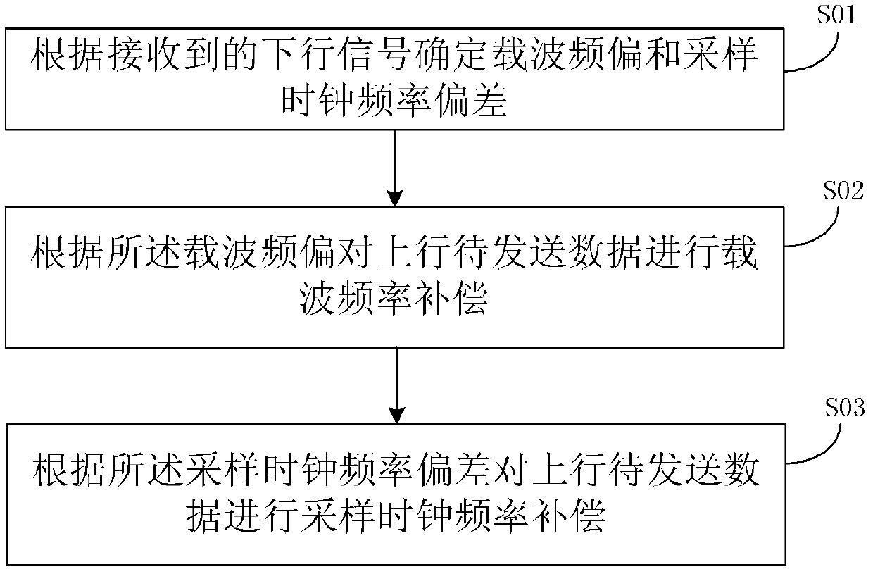
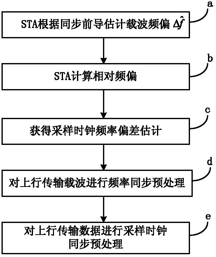
The invention discloses a method for realizing synchronization of a carrier and a sampling clock. The method comprises the steps of: determining a carrier frequency deviation and a sampling clock frequency deviation according to the received downlink signal; carrying out carrier frequency compensation according to uplink to-be-sent data; and carrying out sampling clock frequency compensation according to the uplink to-be-sent data. The invention also provides a user site device, which comprises a carrier frequency deviation measuring unit, a frequency deviation compensating unit, a sampling clock frequency deviation measuring unit and a clock sampling frequency compensating unit. According to the invention, the problem of synchronization of medium-short distance messaging systems based on control is solved, especially, the problem of synchronization when uplink multiple users are accessed in parallel is solved. The synchronization of the time and the frequency is mainly completed by an STA according to a downlink synchronization precursor, the deviation of the frequency and the sampling clock frequency is preprocessed, the synchronization problem is simplified to the signal-user synchronization problem, so that multiple access interference is eliminated without a complicated algorithm when a receiving end separates data of multiple users.

Description

[0001] This application claims that the filing date is 2011.3.25, the application number is 201110074379.7, and the title of the invention is a method, device and wireless communication system for realizing carrier and sampling clock synchronization. reflected in this application. technical field [0002] The present invention relates to the technical field of wireless communication, in particular to a method for realizing synchronization of carrier and sampling clock and user station equipment. Background technique [0003] In communication systems, synchronization is the basis for correct demodulation of information. Generalized synchronization includes time synchronization, frequency synchronization, power adjustment, channel estimation, etc. [0004] In the wireless local area network system based on the IEEE802.11 standard, the communication between the access point AP and the user station STA is a burst mode. ) need to carry synchronization information to assist in c...

Claims


Application Information

Patent Timeline
IPC IPC(8): H04L27/26H04W56/00H04L25/03H04L25/02
Inventor 曾勇波雷俊潘立军王飞飞闫志刚鲍东山
Owner 新岸线(北京)科技集团有限公司
Learn More