Combine harvester

A technology for combine harvesters and harvesting devices, which is applied to harvesters, agricultural machinery and implements, applications, etc., can solve problems such as heavy burdens, and achieve the effects of reducing loads and improving efficiency

Active Publication Date: 2012-10-03
ISEKI & CO LTD
View PDF5 Cites 0 Cited by
  • Summary
  • Abstract
  • Description
  • Claims
  • Application Information

AI Technical Summary

Problems solved by technology

[0004] In the technique described in Patent Document 1, the distance between the left and right grass bodies arranged at the left and right ends of the harvesting section and the center grass body arranged in the center is fixed so that two rows of grain stalks can be introduced into each. interval, so that the harvesting operation can be carried out from 1 row to a maximum of 4 rows of grain stalks, but in this structure, there is the following problem: if the 3 to 4 rows of planted grain stalks are introduced into the harvesting device under the condition of lodging or getting wet, If the load on the reaping device or threshing device becomes too large, it will cause failure due to clogging of grain stalks, etc.

Method used


Image

  • Combine harvester
  • Combine harvester
  • Combine harvester

Examples


Embodiment Construction

[0062] Embodiments of the present invention will be described below with reference to the accompanying drawings.

[0063] In the following description, unless otherwise indicated, the left side when viewed from the operator seated on driver's seat 5 toward the advancing direction of the combine is called left, and the right side is called right.

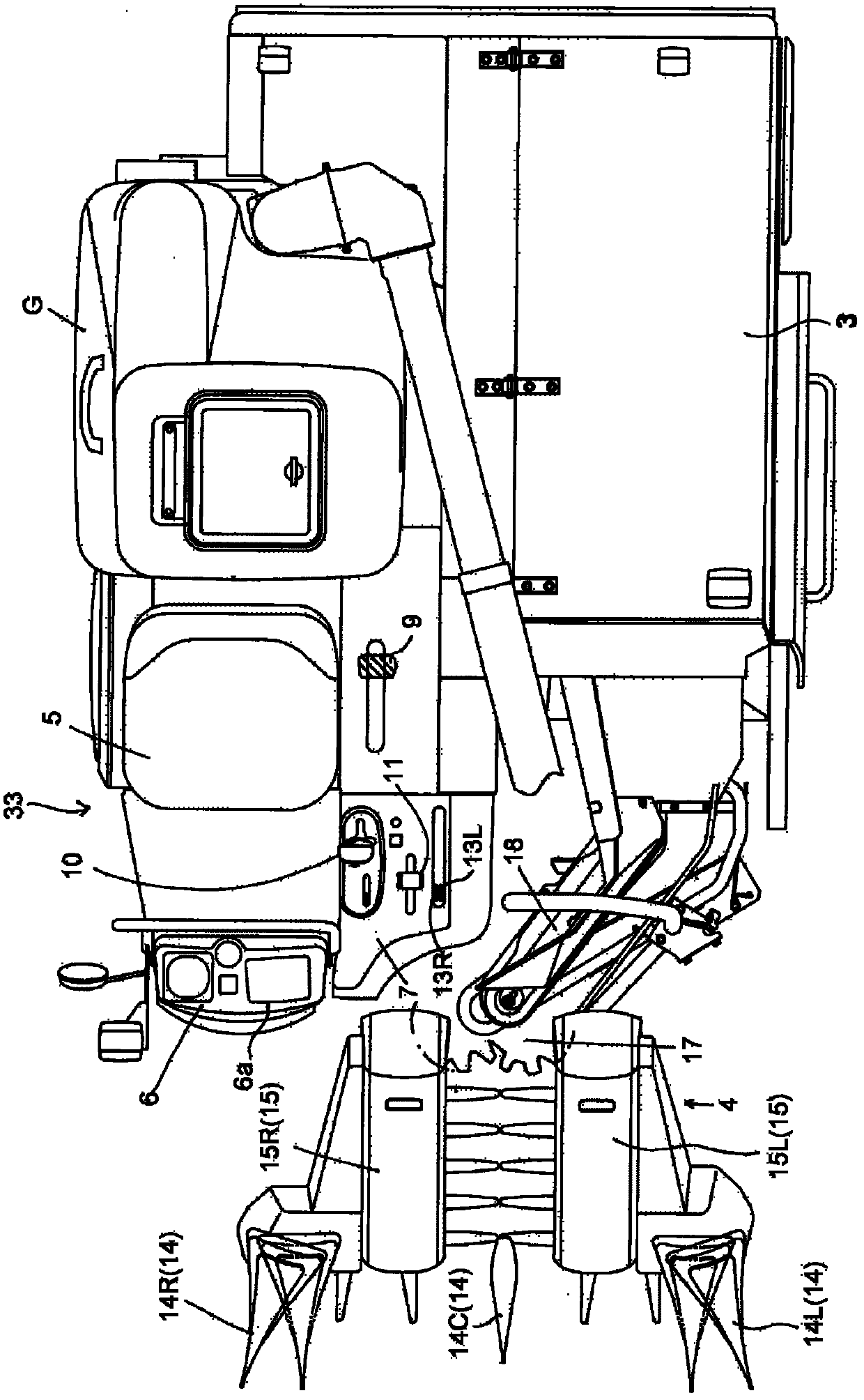
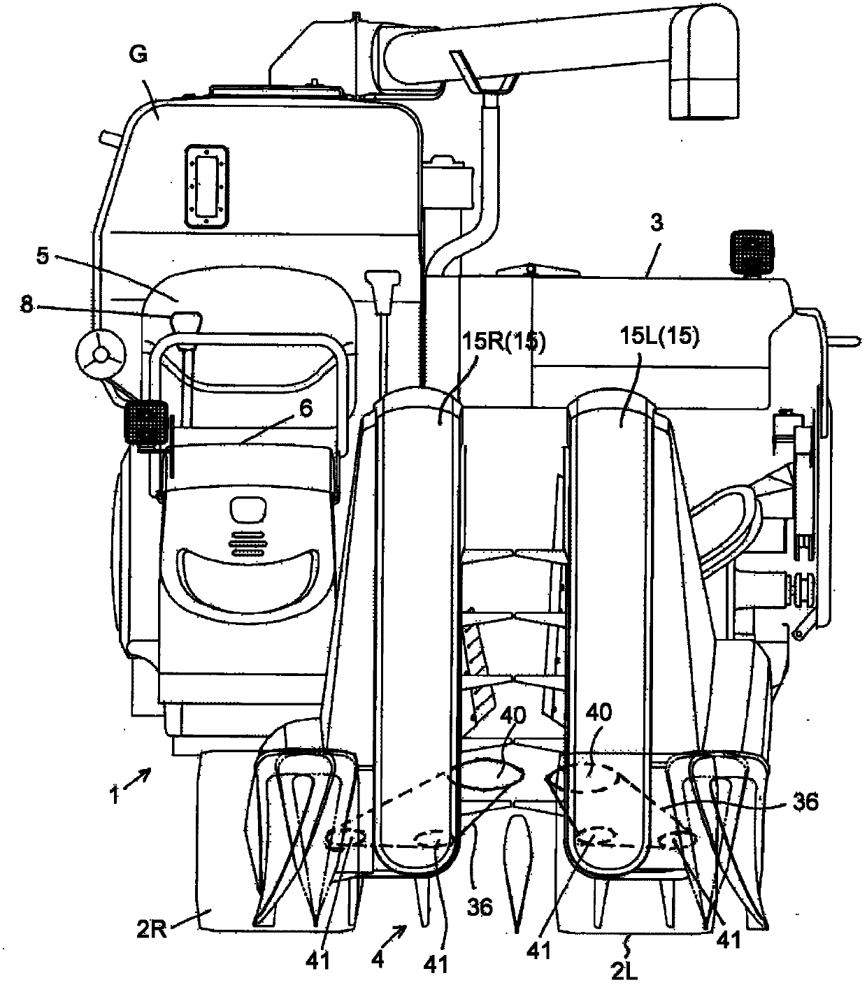
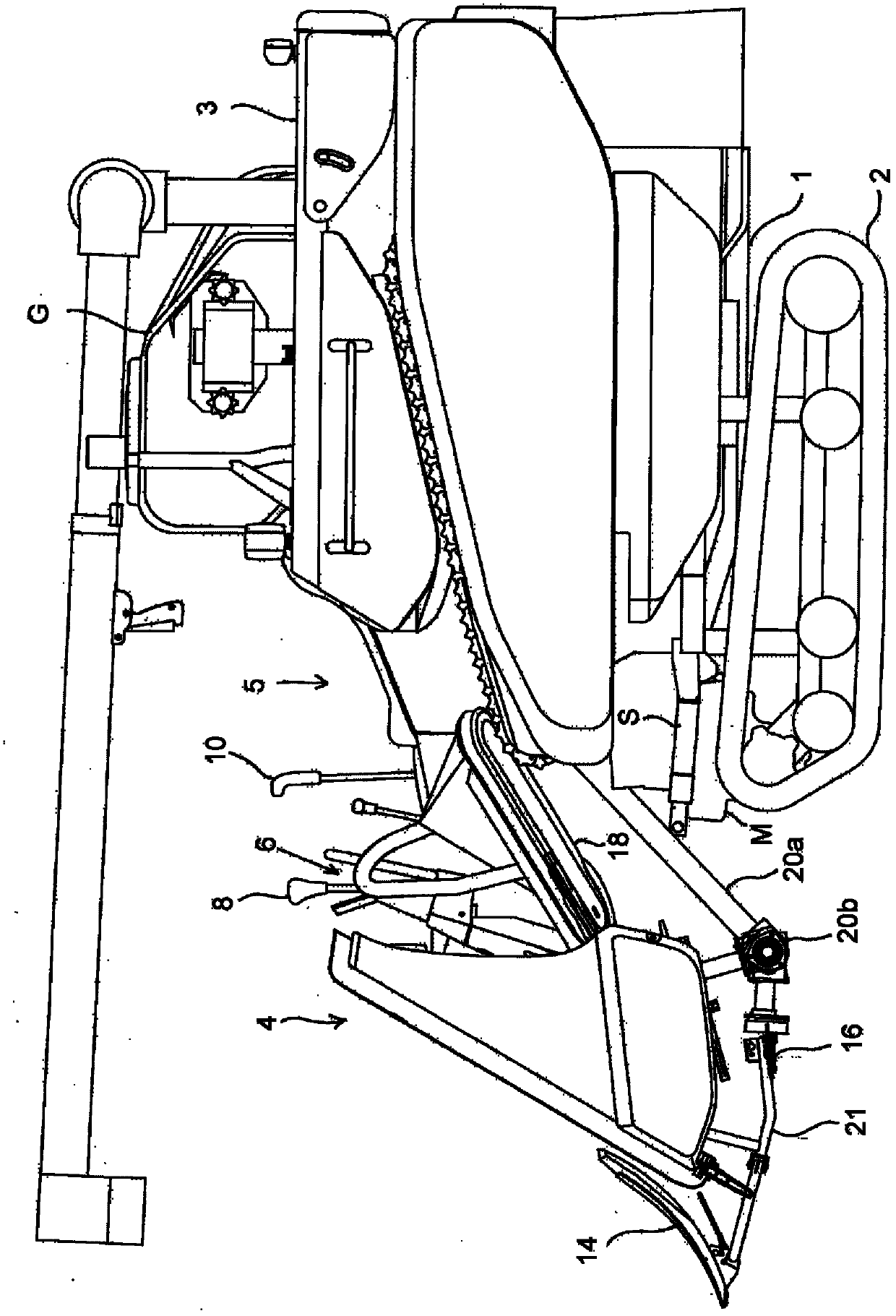
[0064] Figure 1 ~ Figure 3 It shows the whole figure of the combine harvester, and this traveling body 1 is provided with a pair of left and right traveling crawler belts (crawler belts) 2L, 2R as a traveling device 2 driven via a traveling gearbox M, and a threshing belt mounted on the rear The front portion of the device (threshing section) 3 is provided with a harvesting device 4, and the lateral side of the harvesting device 4 is equipped with a driver's seat 5, a front operation box 6 on the front side of the driver's seat, and a side operation box 7 on the lateral left side of the driver's seat. The operation operation part 3...


PUM


Abstract

The present invention provides a combine harvester which can be used for realizing high-effective harvesting works, and preventing blocking of a grain rod caused by load applied on a harvesting device and a threshing device. A tail end part of a left side grass-dividing part (14L) of a left side part of the harvesting device (4) and a tail end of a right side grass-dividing part (14R) of a right side part of the harvesting device (4) are respectively and freely moved toward the right and left directions, thus two rows of grain rods are guided to a part between the left side grass-dividing part (14L) and the right side grass-dividing part (14R) when the tail end part of the left side grass-dividing part (14L) and the tail end part of the right side grass-dividing part (14R) are moved toward the mutually close direction and mutual space is shortened, and four rows of grain rods are guided to a part between the left side grass-dividing part (14L) and the right side grass-dividing part (14R) when the tail end part of the left side grass-dividing part (14L) and the tail end part of the right side grass-dividing part (14R) are moved toward the mutually separating direction and mutual space is enlarged.

Description

technical field [0001] The present invention relates to combine harvesters. Background technique [0002] Conventionally, a combine harvester is known in which a pair of lifting devices for lifting the separated grain stalks are arranged opposite to each other on the left and right, and the movement trajectory of the lifting lugs (lugs) included in these lifting devices is set to form a combined harvester. Dial-in guide area that guides the planted grain stalks between the three grass-distribution bodies that are introduced into the left and right ends and the central grass-distribution body toward the central side of the harvesting and conveying part, and guides the grain stalks that have been dial-in-guided The lifting area of ​​the lifting can realize the expansion of the lifting range (for example, refer to Patent Document 1). [0003] Patent Document 1: Japanese Patent Laid-Open No. 2010-104346 [0004] In the technique described in Patent Document 1, the distance bet...

Claims


Application Information

Patent Timeline
Patent Type & Authority Applications(China)
IPC IPC(8): A01D57/22
Inventor 里路久幸坂本宪之五岛一实
Owner ISEKI & CO LTD
Why Eureka
Try Eureka