
Inverse-vertical wire wrapping machine

A wire take-up machine, inverted technology, applied in the direction of metal wire drawing, metal processing equipment, manufacturing tools, etc., can solve the problems that the wire take-up frame can no longer be used, the wire take-up frame is worn and deformed, and accidents occur, and the structure is simple , Increased service life and easy operation

Inactive Publication Date: 2012-10-03
WUXI PINGSHENG SCI & TECH
View PDF7 Cites 12 Cited by
  • Summary
  • Abstract
  • Description
  • Claims
  • Application Information

AI Technical Summary

Problems solved by technology

[0003] The take-up stand of the original inverted take-up machine is connected to the take-up pulley through a lever sleeve, and the take-up pulley drives the take-up stand to rotate and take up the line. When replacing the take-up stand, the take-up stand and the drive lever must The cover is in a proper relative position and must be pushed in quickly, otherwise there will be an accident due to the rotation of the lever cover to turn the take-up frame down, and the operation is troublesome
At the same time, there are strict requirements on the height of the take-up frame, and the take-up frame will be worn and deformed after a period of use, which makes many take-up frames unable to continue to be used.

Method used


Image

  • Inverse-vertical wire wrapping machine
  • Inverse-vertical wire wrapping machine

Examples


Embodiment Construction

[0014] Below the present invention will be further described in conjunction with the embodiment in the accompanying drawing:

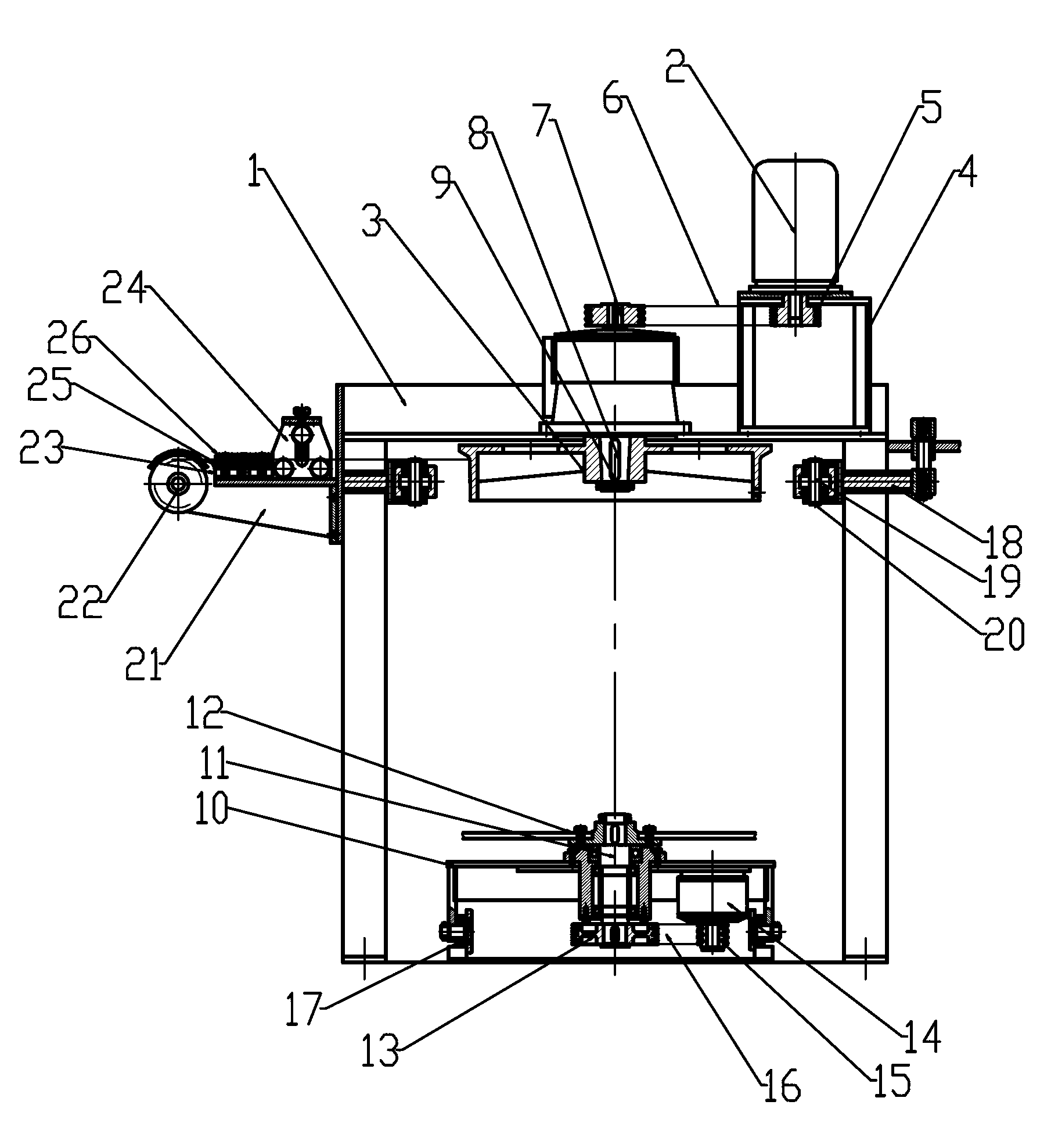
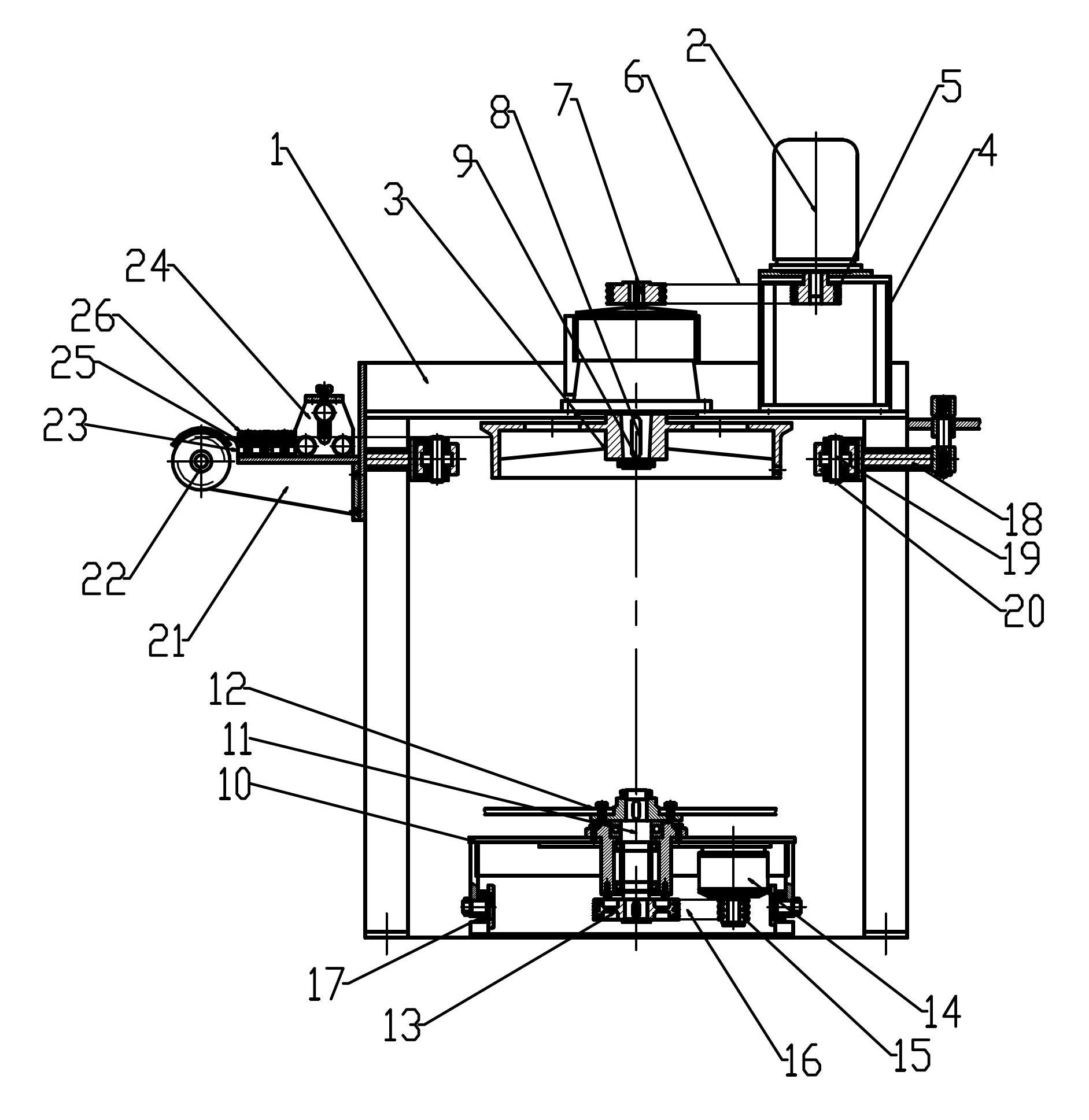
[0015] Such as figure 1 As shown, the present invention mainly includes a frame 1, a motor 2, a reel 3, a take-up trolley 10, a take-up rack 12, a speed reducer 14, a cylinder 18, a pressure roller 20, a straightening bracket 21, a wire guide wheel 22, Horizontal seat board 23, vertical seat board 24 and straightening wheel 26.

[0016] A reel shaft 8 is installed in the middle of the top of the frame 1 , and the lower end of the reel shaft 8 is connected to the reel 3 and fastened by a nut 9 . The upper end of the reel shaft 8 is connected with the reel pulley 7 . The frame 1 next to the reel 3 is connected with a motor base 4, and a motor 2 is installed on the motor base 4, and the shaft end of the motor 2 is connected with a motor pulley 5. The reel pulley 7 is driven to rotate by the motor pulley 5 through the first synchronous belt 6 .

[0017...


PUM


Abstract

The invention relates to an inverse-vertical wire wrapping machine, which specifically is used for winding metal lines and belongs to the technical field of metal drawing equipment; the inverse-vertical wire wrapping machine mainly comprises a machine frame, a motor, a winding drum, a wire wrapping trolley, a wire wrapping frame, a decelerator, a cylinder, a pinch roller, an aligning bracket, a threading guide wheel, a horizontal bottom board, a vertical base board and an aligning wheel; according to the invention, the structure of the inverse-vertical wire wrapping machine is simple, compact and reasonable; the wire wrapping frame is rotated through driving of the independent decelerator, so that adjustable circle diameters of metal wires are realized; speed is synchronous to a main shaft pulley; the inverse-vertical wire wrapping machine is operated conveniently; workload is reduced; work efficiency is increased; because a poking rod sleeve is cancelled, service life of the wire wrapping machine is prolonged greatly.

Description

technical field [0001] The invention relates to an inverted wire take-up machine, specifically for winding metal wires, and belongs to the technical field of metal drawing equipment. Background technique [0002] In the prior art, the inverted wire take-up machine is a device for drawing high-strength, thick-gauge prestressed metal wires. It winds the annealed steel wire to the take-up frame according to the take-up speed required by different diameters. When the take-up frame winds to a fixed length, the wire is dropped onto the trolley and removed, so as to realize continuous take-up. [0003] The take-up stand of the original inverted take-up machine is connected to the take-up pulley through a lever sleeve, and the take-up pulley drives the take-up stand to rotate and take up the line. When replacing the take-up stand, the take-up stand and the drive lever must The cover is in a suitable relative position and must be pushed in quickly, otherwise an accident will occur d...

Claims


Application Information

Patent Timeline
Patent Type & Authority Applications(China)
IPC IPC(8): B21C47/04B21C19/00
Inventor 顾康建
Owner WUXI PINGSHENG SCI & TECH
Learn More