Crane with good stability

A crane and stability technology, applied in the field of cranes, can solve the problem of low positioning accuracy and achieve the effect of good integrity, not easy to deform, and high rigidity

Inactive Publication Date: 2012-10-03
河南省新乡市矿山起重机有限公司
View PDF5 Cites 6 Cited by
  • Summary
  • Abstract
  • Description
  • Claims
  • Application Information

AI Technical Summary

Problems solved by technology

But the positioning accuracy of the spreader in the prior art is not high

Method used


Image

  • Crane with good stability
  • Crane with good stability
  • Crane with good stability

Examples


Embodiment Construction

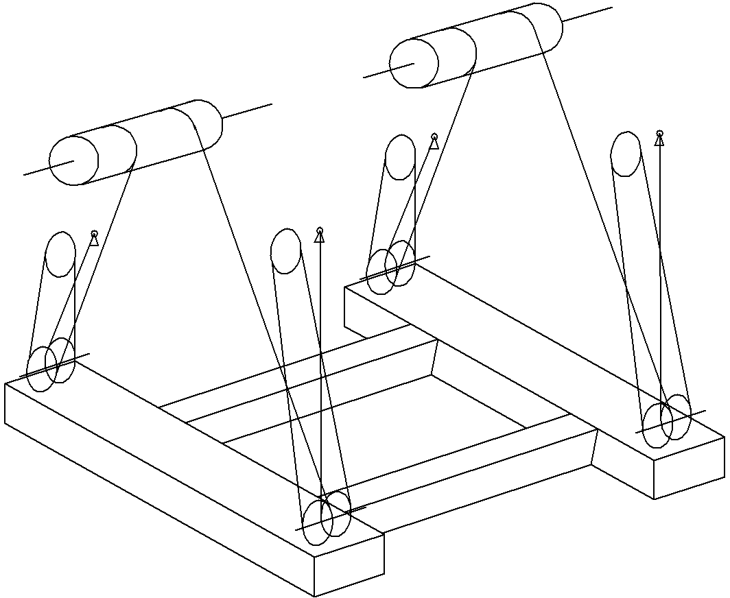
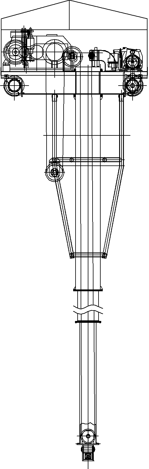
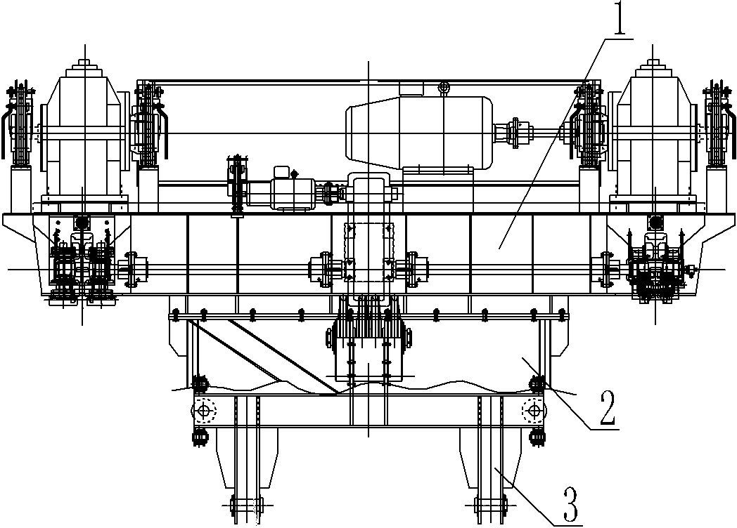
[0025] An embodiment of a crane with good stability, in Figure 3~14 Among them, the trolley set on the main girder of the crane is as follows: image 3 , 4 , 5, the lower part of the trolley frame 1 of the trolley is hoisted with a spreader 3, the spreader 3 has a crossbeam 4, the crossbeam 4 is horizontally arranged below the trolley frame 1, and the upper part of the crossbeam 4 is provided with a movable pulley 10 for rotation, A wire rope is wound between the movable pulley 10 and the fixed pulley arranged on the trolley frame 1 , and the wire rope here hangs the sling under the trolley frame 1 . Basically, the spreader of the crane and the trolley frame are connected by wire ropes wound between the movable pulley of the spreader and the reel of the trolley frame, which will not be described in detail here.

[0026] Both ends of the beam 4 are provided with large guide wheels 8, and the outer peripheral surfaces of the two large guide wheels 8 respectively protrude from...


PUM


Abstract

The invention discloses a crane with good stability. The crane comprises a main beam, wherein a trolley is movably arranged on the main beam; the trolley comprises a trolley frame; a lifting appliance is arranged under the trolley frame in a lifting manner; the lifting appliance comprises a beam, and a movable pulley is arranged on the upper part of the beam; the lifting appliance is arranged on the trolley frame in a lifting manner through a steel wire rope wound on the movable pulley and a rotary drum arranged on the trolley frame; rotary shafts are arranged on the end surface parts of the two ends of the beam and are vertical to large guide wheels in the extending direction of the beam; rotary shafts are arranged on the two end parts at the two sides of the beam and are in parallel with small guide wheels in the extending direction of the beam; a guiding frame is fixed on the lower part of the trolley frame; the guiding frame is provided with a guide rail pair and limit guide rails at two ends of the beam; the two guide rails of the guide rail pair are respectively in rolling and limit fit with the small guide wheels at the two sides of the corresponding end of the beam; and the limit guide rails are respectively in rolling and limit fit with the large guide wheels at the corresponding end of the beam.

Description

technical field [0001] The invention relates to a crane, in particular to a crane with good stability used in the field of metallurgy. Background technique [0002] The application range of the crane is very wide. The crane generally includes a main girder, and a trolley is installed on the main girder. On the frame, during the movement of the trolley, the spreader and the goods will inevitably sway, which seriously affects the working performance of the crane. In order to ensure the stability of the spreader, anti-sway devices are installed on the crane. figure 1 Shown in is a schematic structural diagram of a typical anti-swing wire rope winding system in the prior art. This structure reduces the overall shaking through the restraint of the wire rope, and makes a positive contribution to reducing the shaking of the crane. Swing, and eventually the swing of the crane spreader cannot be completely avoided. In order to realize the precise positioning of the spreader o...

Claims


Application Information

Patent Timeline
Patent Type & Authority Applications(China)
IPC IPC(8): B66C19/00
Inventor 任会江蔡迎新洪亮林浩靳思德赵武生
Owner 河南省新乡市矿山起重机有限公司
Why Eureka
Try Eureka