Supercharge Your Innovation With Domain-Expert AI Agents!

A password unlocking mechanism for electronically controlled locks

An electronically controlled lock and password technology, which is applied to electric alarm locks, building locks, building structures, etc., can solve the problems of the safety factor of electronically controlled anti-theft locks, etc., and achieve good anti-theft effect and simple operation

Inactive Publication Date: 2015-08-26
欧阳满桂
View PDF6 Cites 0 Cited by
  • Summary
  • Abstract
  • Description
  • Claims
  • Application Information

AI Technical Summary

Problems solved by technology

[0002] The setting of the unlocking password on the existing electronically controlled lock is realized by editing the control program. With the continuous maturity of technology, more and more people have mastered the cracking of the unlocking password. device, making the safety factor of electronically controlled anti-theft locks continue to decline

Method used


Image

  • A password unlocking mechanism for electronically controlled locks
  • A password unlocking mechanism for electronically controlled locks
  • A password unlocking mechanism for electronically controlled locks

Examples


Embodiment 1

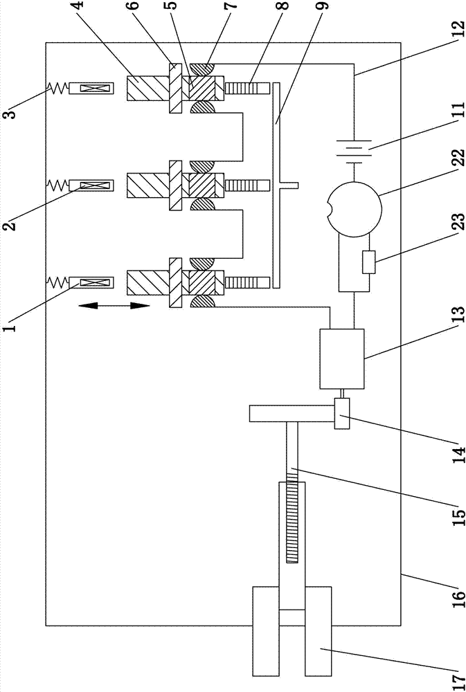
[0029] Embodiment one, such as Figure 1 to Figure 4 As shown, the password unlocking mechanism for electronically controlled locks includes at least one group of unlocking electrodes consisting of two contacts 7 in an open circuit state, and the unlocking electrodes are used to be connected in series in the unlocking drive circuit 12; the password unlocking mechanism corresponds to each A lock wheel 4 is provided for the rotation of the group unlocking electrode, and the lock wheel 4 is arranged between the two contacts 7 of the unlock electrode, and the two contacts 7 deviate from the center of the lock wheel 4, and the lock wheel 4 is provided with a mechanism to make the two contacts pass by. Conductive conduction part; the side of the lock wheel 4 is provided with a driver that drives the lock wheel 4 to rotate, and a reset device that restores the lock wheel 4 to its original state.

[0030] The conduction part of the lock wheel 4 is the conductor 5 that runs through bot...

Embodiment 2

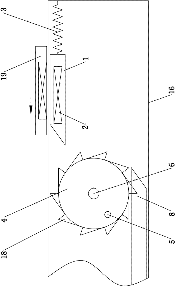
[0037] Embodiment two, its difference with embodiment one is: as Figure 5 As shown, the driver includes a push key 1 and an extension spring 3, the push key 1 is slidably arranged in the lock housing 16, one end of the push key 1 points to the ratchet of the lock wheel 4, and the other end is connected with an end of the extension spring 3, and the extension spring 3. The other end is fixedly connected to the lock case 16. A handle 20 is provided on the top of the push key 1, and the handle 20 extends out of the lock case 16.

Embodiment 3

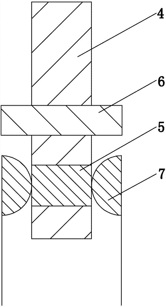
[0038] Embodiment three, its difference with embodiment one is: as Figure 6 As shown, the conduction portion of the lock wheel 4 is a avoidance hole 21 connected to both sides of the lock wheel 4, and the two contacts 7 of the unlocking electrode slide through the avoidance hole 21 to contact and conduct each other. The lock wheel 4 is made of insulating material production.


PUM


Abstract

The invention relates to a password unlocking mechanism used for an electronic control lock, which comprises at least one group of unlocking electrodes, wherein the unlocking electrodes are formed by two contacts under the open circuit status; the unlocking electrodes are used to be connected in an unlocking driving circuit in series; the password unlocking mechanism is provided with a lock wheel in a rotating mode by corresponding to each group of unlocking electrodes; each lock wheel is arranged between the two contacts of the corresponding unlocking electrodes, the two contacts are deviated from the center of the lock wheel, and the lock wheel is provided with a conduction part which enables to conduct electricity when the two contacts pass. According to the electronic control lock, the lock wheels are enabled to rotate for a specific angle around a shaft by an actuator, the two contacts of the unlocking electrodes are conducted, the unlocking driving circuit is electrified, and unlocking is controlled. The initial positions of the conduction parts of the lock wheel in each group of unlocking electrodes are different, so that the rotating angle of each lock wheel can be controlled to form different combinations during unlocking so as to form unlocking passwords, and the unlocking passwords are cracked in a mechanical regulation mode and cannot be cracked by a decoder.

Description

technical field [0001] The invention relates to the technical field of electronically controlled locks, in particular to a password unlocking mechanism for electronically controlled locks. Background technique [0002] The setting of the unlocking password on the existing electronically controlled lock is realized by editing the control program. With the continuous maturity of technology, more and more people have mastered the cracking of the unlocking password. device, making the safety factor of the electronically controlled anti-theft lock continue to decline. [0003] In Chinese Patent No. CN201120218033.5, and on March 28, 2012, I disclosed a safety and anti-theft lock, which includes a lock body and a key thereof. The lock body is mainly composed of a housing, several key positions and a lock bolt. The lock key position is a metal conductive electrode, and several lock key positions form an open-circuit unlocking electrode with at least two lock key positions as a gro...

Claims


Application Information

Patent Timeline
Patent Type & Authority Patents(China)
IPC IPC(8): E05B47/02E05B45/08E05B15/00
Inventor 欧阳满桂
Owner 欧阳满桂
Features
  • R&D
  • Intellectual Property
  • Life Sciences
  • Materials
  • Tech Scout
  • Unparalleled Data Quality
  • Higher Quality Content
  • 60% Fewer Hallucinations
Learn More