Device and method for detecting drilling fluid return flow

A flow detection device and flow detection technology, which are used in earth-moving drilling, flushing wellbore, wellbore/well components, etc., can solve the problems of large error, low precision, and delay in reflection, and achieve small cross-sectional width and real-time performance. The effect of good sex and reducing requirements

Inactive Publication Date: 2012-10-03
SOUTHWEST PETROLEUM UNIV
View PDF6 Cites 10 Cited by
  • Summary
  • Abstract
  • Description
  • Claims
  • Application Information

AI Technical Summary

Problems solved by technology

[0004] The purpose of the present invention is to overcome the deficiencies of the prior art, to provide a drilling fluid return flow detection device and method, which solves the problem of low precision and lagging reflection of the current mud return flow measurement device, especially when the flow rate is small, the error is large major issues

Method used


Image

  • Device and method for detecting drilling fluid return flow
  • Device and method for detecting drilling fluid return flow
  • Device and method for detecting drilling fluid return flow

Examples


Embodiment Construction

[0022] The present invention will be further described below in conjunction with the accompanying drawings, but the protection scope of the present invention is not limited to the following description.

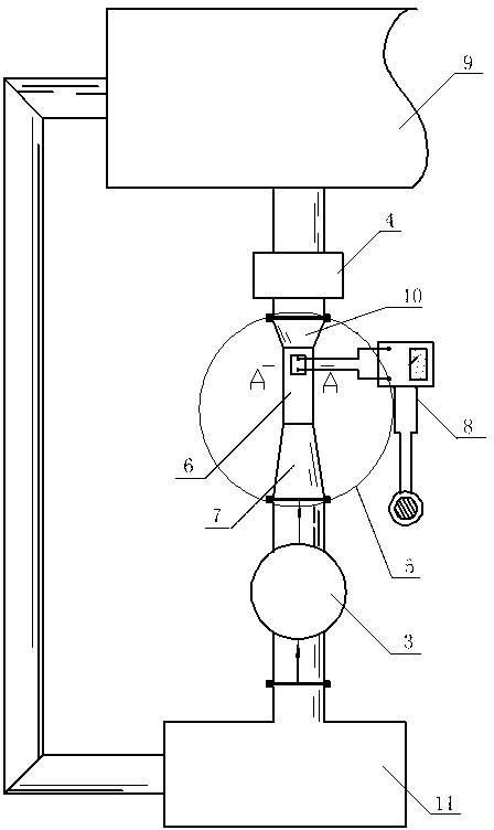
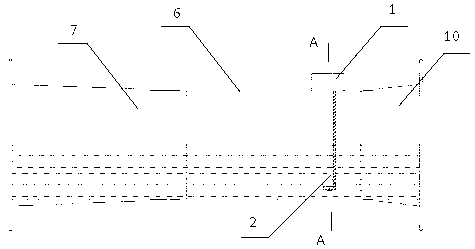
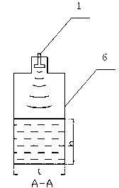
[0023] Such as figure 1 , figure 2 , image 3 As shown, a drilling fluid return flow detection device is composed of one or more flow measurement nipples 5 installed between the wellbore drilling fluid return outlet 3 and the vibrating screen 4, and the flow measurement nipples 5 include Rectangular section flow section 6 and bell mouth buffer sections located at both ends of rectangular section flow section 6, liquid level sensor 1 is installed on the top of rectangular section flow section 6, flow velocity sensor 2 is installed in the internal liquid flow of rectangular section flow section 6 , the liquid level sensor 1 and the flow rate sensor 2 are electrically connected to the calculation and display alarm unit 8 respectively.

[0024] A drilling fluid return flow de...


PUM


Abstract

The invention discloses a device and a method for detecting drilling fluid return flow. The device comprises one or more flow measuring short sections (5) arranged between a drilling fluid return port (3) of a shaft and a vibration screen (4); the flow measuring short sections comprise a rectangular-cross-section overflow section (6) and a horn mouth buffer section at two ends of the rectangular-cross-section overflow section (6); a fluid level sensor (1) is installed on the top of the rectangular-cross-section overflow section (6); a flow speed sensor (2) is installed inside the internal fluid in the rectangular-cross-section overflow section (6); and the fluid level sensor (1) and the flow speed sensor (2) are respectively connected with a calculation and display alarming unit (8) electrically. With the adoption of the device and method for detecting the drilling fluid return flow, the problems that an existing mud return flow measuring device is not high in precision, delayed in reaction, larger in error especially when the flow is smaller and the like are solved; the measuring section adopts a rectangular cross section that the fluid level and the height are in linear change; the requirements of flow detecting equipment on the calculation means are reduced; and the device and method for detecting drilling fluid return flow is high in measurement precision and good in timeliness.

Description

technical field [0001] The invention belongs to the technical field of oil and gas drilling testing, and relates to an open channel flow detection device and method, in particular to a drilling fluid return flow detection device and method. Background technique [0002] In the process of oil drilling, the amount of mud return is a very important parameter, which is related to the instant indication of well kick and lost circulation, and is the premise of implementing well control in advance and preventing blowout. [0003] At present, the drilling fluid return flow is usually measured in the mud tank in the oil drilling industry, and the return flow of the drilling fluid is reflected by measuring the liquid level change in the mud tank. Flow reflection lag and other shortcomings; another commonly used target flowmeter is installed on the drilling fluid return pipeline, which is composed of a swing target and an angle sensor. When the mud hits the pendulum target at a certai...

Claims


Application Information

Patent Timeline
Patent Type & Authority Applications(China)
IPC IPC(8): E21B21/08G08B21/00
Inventor 王国荣谢冲程俊丰刘清友
Owner SOUTHWEST PETROLEUM UNIV
Why Eureka
Try Eureka