Crank and radius regulating device thereof

A technology of adjusting device and crank radius, applied in crank, transmission, belt/chain/gear, etc., can solve problems such as inability to perform real-time adjustment, difficult adjustment of frame length, and large overall weight of the machine. Quick and easy effects

Inactive Publication Date: 2012-10-03
CHONGQING TECH & BUSINESS UNIV
View PDF5 Cites 5 Cited by
  • Summary
  • Abstract
  • Description
  • Claims
  • Application Information

AI Technical Summary

Problems solved by technology

[0005] However, for large-scale machinery, the overall weight of the machine is very large, and it is very difficult to adjust the length of the rack, and the adjustment of the length of the rack can only be adjusted after the machine is stopped. Whether the length of the rod adjusted by the tes

Method used


Image

  • Crank and radius regulating device thereof
  • Crank and radius regulating device thereof
  • Crank and radius regulating device thereof

Examples


Embodiment Construction

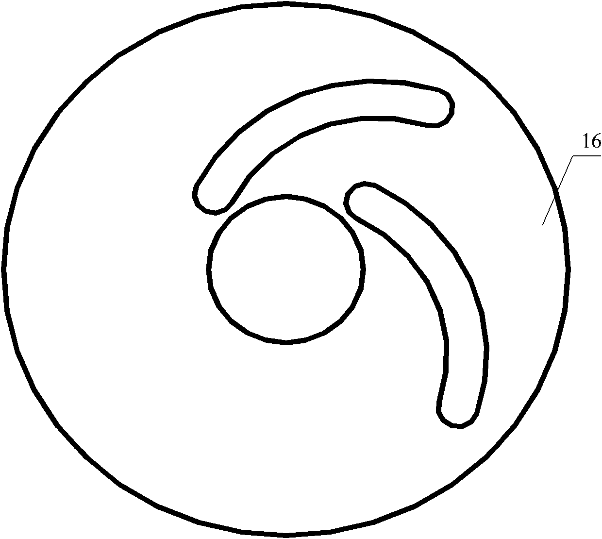
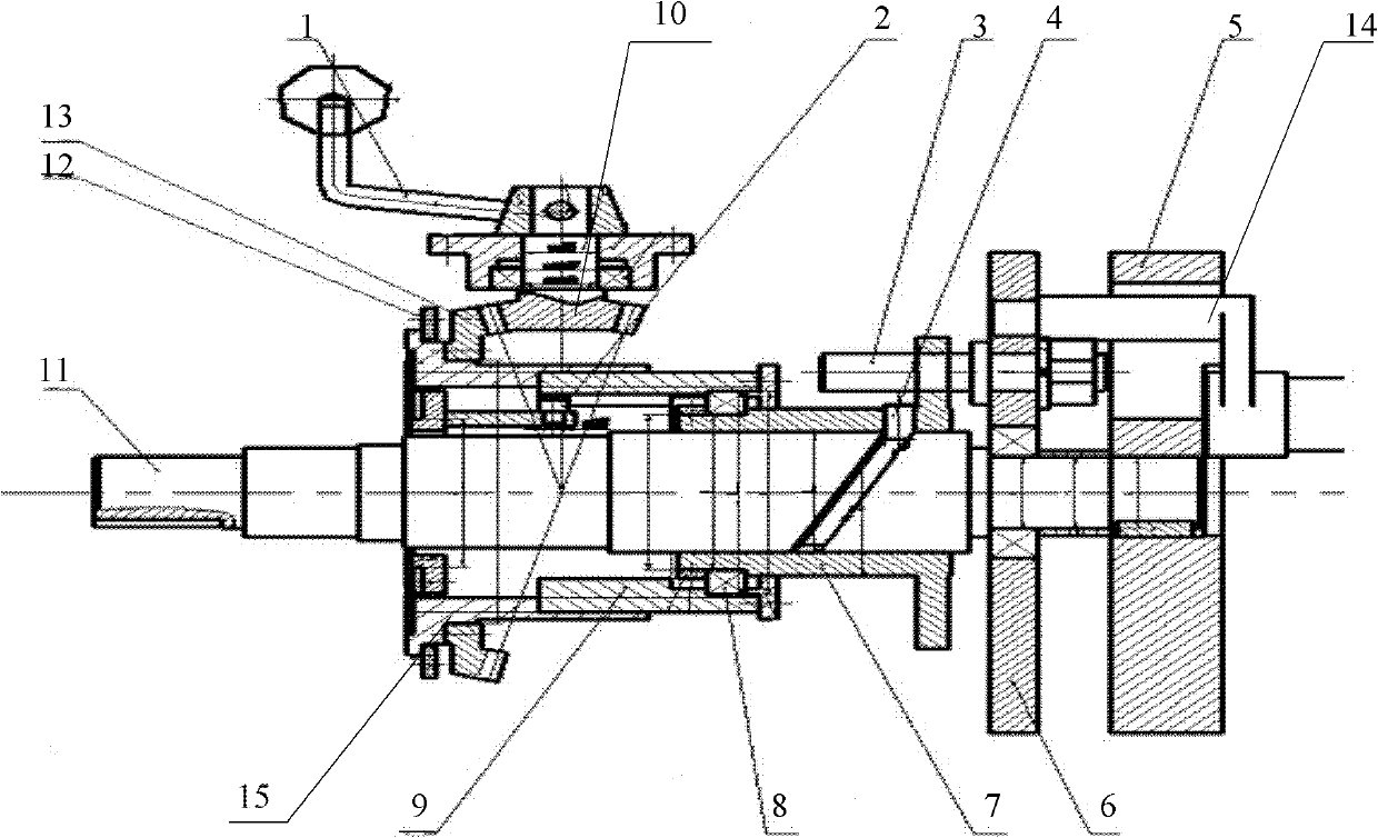
[0034] The core of the present invention is to provide a crank and its adjusting device. The crank is used in a pulse-type continuously variable transmission. Since the crank includes a crank cam and a first crank rod installed on the crank cam, the first crank rod can pass through The arc groove on the crank cam adjusts the radius of the crank, thereby changing the output speed. Meanwhile, the invention also discloses an adjusting device for adjusting the radius of the crank.

[0035] In order to enable those skilled in the art to better understand the solutions of the present invention, the present invention will be further described in detail below in conjunction with the accompanying drawings and specific embodiments.

[0036] Please also refer to the attached figure 1 And attached image 3 , with figure 1 The schematic diagram of the crank cam structure of the crank provided by the present invention, attached image 3 It is a structural schematic diagram of the crank r...


PUM


Abstract

The invention discloses a crank with adjustable center distance, which is used for regulating output speed of a pulse stepless transmission. The crank comprises a crank cam and a crank rod, wherein the crank rod is mounted on the crank cam through an arc-shaped groove on the crank cam in a slidable manner, and the distances from all points on the arc-shaped groove to the rotation center of the crank cam are different, so that the radius of the crank can be changed continuously along with the sliding of the crank rod and the regulation of the output speed can be realized; the regulating device is simple, convenient and easy to regulate speeds of large-scale machineries; and simultaneously, the invention further discloses a device for regulating the radius of the crank, and the regulation of the radius of the crank can be realized by adopting the device.

Description

technical field [0001] The invention relates to the technical field of transmission design, in particular to a crank with adjustable center distance and a radius adjusting device thereof. Background technique [0002] In modern machinery, transmissions are generally installed, and a single speed can no longer meet the diverse needs of people. The function of the transmission is to change the transmission ratio between the input end and the output end, thereby changing the output speed. [0003] The basic structural model of the pulsating continuously variable transmission is a crank rocker mechanism. As we all know, the adjustment of the output speed of the rocker is realized by changing the length ratio of each rod. After the production of the pulsating continuously variable transmission is completed, the adjustable part There are only two adjustable parts, the length of the frame and the length of the crank, and the other connecting rods and rockers are not adjustable. ...

Claims


Application Information

Patent Timeline
IPC IPC(8): F16C3/28F16H21/20
Inventor 杜力康华领任亨斌陈亚华
Owner CHONGQING TECH & BUSINESS UNIV
Why Eureka
Try Eureka