
Tension detecting device

A technology of tension detection and pressing plate, which is applied in the direction of measuring devices, measuring force, instruments, etc., can solve problems such as troublesome operation and difficult guarantee, and achieve the effects of simple structure, improved accuracy, and convenient measurement process

Inactive Publication Date: 2012-10-03
昆山沪光汽车电器股份有限公司
View PDF10 Cites 6 Cited by
  • Summary
  • Abstract
  • Description
  • Claims
  • Application Information

AI Technical Summary

Problems solved by technology

The measuring head of the tension meter has a spiral structure, and the parts used to fix the measuring head and the fixing parts are generally hooks. In actual operation, it is often necessary to add other parts such as wires to fix the connection, which is troublesome to operate and difficult to ensure. The direction of the final force is consistent with the direction of the central axis of the measuring head

Method used


Image

  • Tension detecting device
  • Tension detecting device
  • Tension detecting device

Examples


Embodiment Construction

[0013] The present invention will be further described below in conjunction with the accompanying drawings.

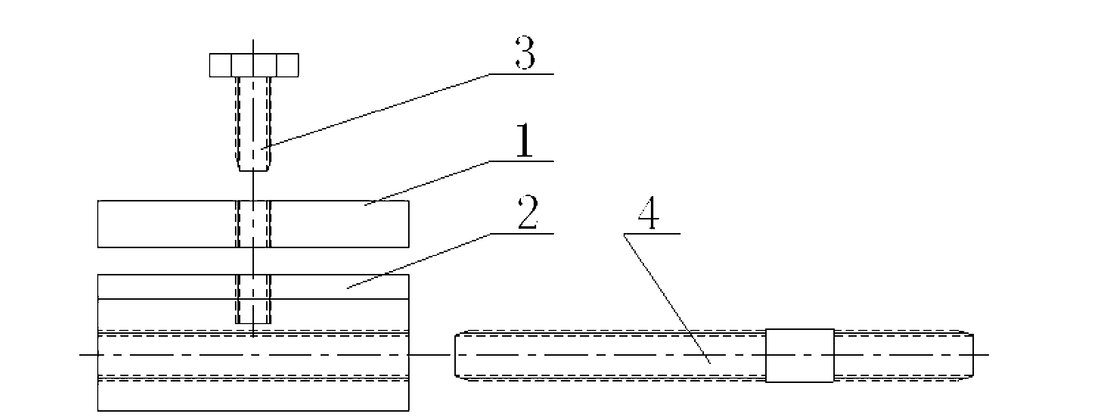
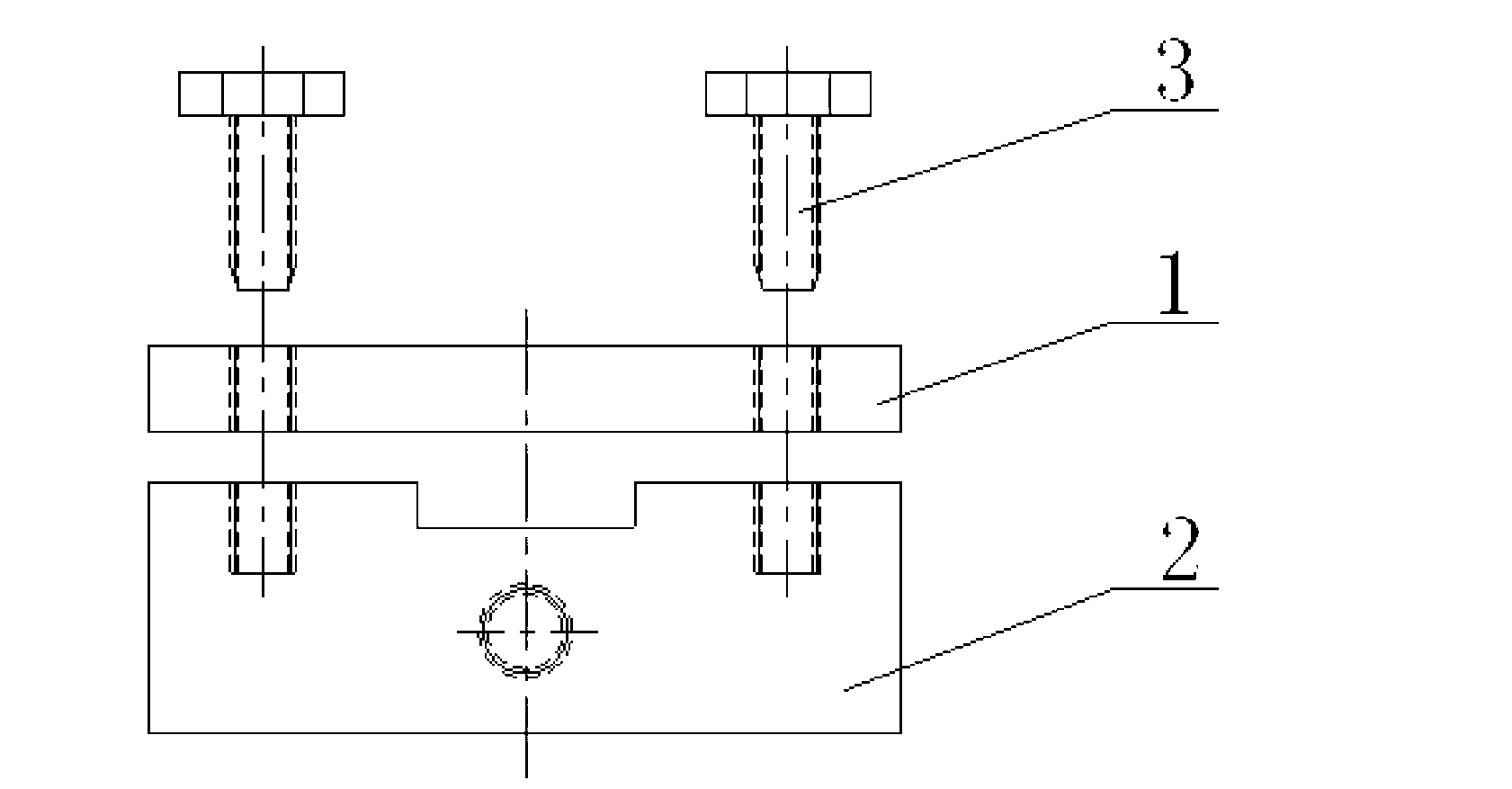
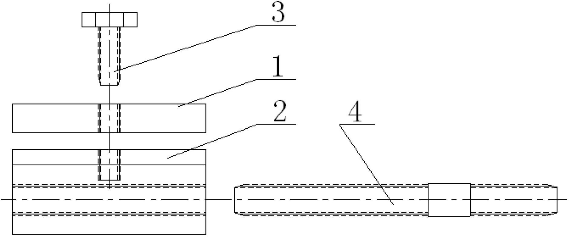
[0014] Such as figure 1 , figure 2 Shown is a tension detection device, which includes an upper pressing plate 1, a lower pressing block 2, a pair of bolts 3 and a connecting screw 4. Both the upper pressing plate 1 and the lower pressing block 2 are square structures.

[0015] The upper side of the lower pressing block 2 is provided with a square groove communicating with its left and right sides, the upper pressing plate 1 and the lower pressing block 2 are fixed by bolts 3, the lower side of the square groove and the lower side of the upper pressing plate 1 on it Constituting the pressing surface of the upper and lower sides of the fixed part under inspection, the paired bolts 3 are respectively located at the relative positions on the front and rear sides of the square groove;

[0016] The left end of the connecting screw 4 is fixed with the lower pressing block...


PUM


Abstract

The invention discloses a tension detecting device, comprising an upper pressing plate, a lower pressing block, paired bolts and a connecting screw rod, wherein the upper side face of the lower pressing block is provided with a square slot for communicating the left side face and the right side face of the lower pressing block, and the upper pressing plate and the lower pressing block are fixed through the bolts; the lower side face of the square slot and the lower side face of the upper pressing plate positioned on the lower side face of the square slot form a seal face of the upper side face and the lower side face of a detected fixed part; the paired bolts are respectively positioned on opposite positions at front and back sides of the square slot; and the left end of the connecting screw rod is fixed with the lower pressing block through a threading structure, the right end of the connecting screw rod is fixed with a measuring head of a tensometer through a threading structure, and the central axis of the connecting screw rod is consistent with the central axis of the measuring head of the tensometer. The tension detecting device disclosed by the invention has a simple structure and is convenient to use; and by adopting the tension detecting device, the detected fixed part can be ensured to be effectively fixed without generating additional force on a detected movable part, the accuracy of the force application direction can be improved when the detected part is detected, the measurement process is convenient, and the measurement precision is improved.

Description

technical field [0001] The invention relates to a tension detection device, in particular to a tension detection device suitable for use with a tension meter. Background technique [0002] Tension gauge is a small and simple thrust and tension testing instrument; it has the advantages of high precision, easy operation and portability, and has a peak value switching operation knob, which can be used for peak load indication and continuous load value indication. In the factory, a tension meter is often used to perform simple tensile performance tests on products or parts; when in use, fix the fixed part with the measuring head of the tension meter, and pull the movable part along the central axis of the tension meter measuring head to obtain the measurement result . The measuring head of the tension meter has a spiral structure, and the parts used to fix the measuring head and the fixing parts are generally hooks. In actual operation, it is often necessary to add other parts ...

Claims


Application Information

Patent Timeline
Patent Type & Authority Applications(China)
IPC IPC(8): G01L1/00G01L1/26
Inventor 成三荣
Owner 昆山沪光汽车电器股份有限公司
Learn More