
Simulation test device for pneumatic load of vehicle body

An aerodynamic load and simulation test technology, applied in the field of car body aerodynamic load simulation test, can solve the problems of high airtightness of the tank body, great difficulty in processing, high processing cost, etc., and achieve low cost, short cycle, and test convenient effect

Active Publication Date: 2012-10-03
CRRC TANGSHAN CO LTD
View PDF5 Cites 17 Cited by
  • Summary
  • Abstract
  • Description
  • Claims
  • Application Information

AI Technical Summary

Problems solved by technology

[0003] The prior art usually adopts a cylindrical tank body, the bottom of which is provided with guide rails, and the car body to be tested is sent into the tank body by means of a process bogie, and then the car body to be tested is sealed in the tank body, and passed to the sealed tank body. Gas is introduced into the body to carry out the pressure test on the car body. During the test, the airtightness of the tank body is very high, and it is very difficult to process the tank body that can accommodate the entire car body. The existing tank body Usually only part of the car body (maximum 1 / 3 of the car body) can be pressure tested. During the test, it is necessary to connect the car body to be tested and the tank body through the end cover to ensure that the car body part placed inside the tank body is in a In order to carry out effective pressure tests in the sealed space, due to the differences in the dimensions and structures of different types of car bodies, different end covers are usually required to seal the tank body, which has poor versatility. In addition, the tank body is a pressure vessel, and the processing cost high

Method used


Image

  • Simulation test device for pneumatic load of vehicle body
  • Simulation test device for pneumatic load of vehicle body
  • Simulation test device for pneumatic load of vehicle body

Examples


Embodiment 1

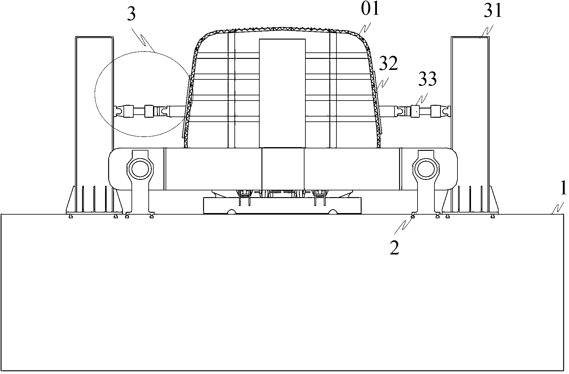
[0011] Such as figure 1 As shown, the car body aerodynamic load simulation test device provided by the present invention consists of a test bench 1, a fixing mechanism 2 for fixing the two ends of the car body 01 to be tested on the test bench, and a fixing mechanism 2 for fixing the two ends of the car body to be tested. The horizontal pressing mechanism 3 for applying pressure is composed of; wherein, the horizontal pressing mechanism 3 is composed of a plurality of pressing components, and the pressing component is composed of a column 31, a wind pressure plate 32 and a hydraulic actuator 33, and the bottom of the column 31 is fixed on the test bench 1, one end of the hydraulic actuator 33 is hinged to the column 31, and the other end is hinged to one side of the air pressure plate 32; the other side of the air pressure plate 32 is connected to the side wall of the vehicle body 01 to be tested. The hydraulic actuator 33 can be directly purchased in the market, and the hinge...

Embodiment 2

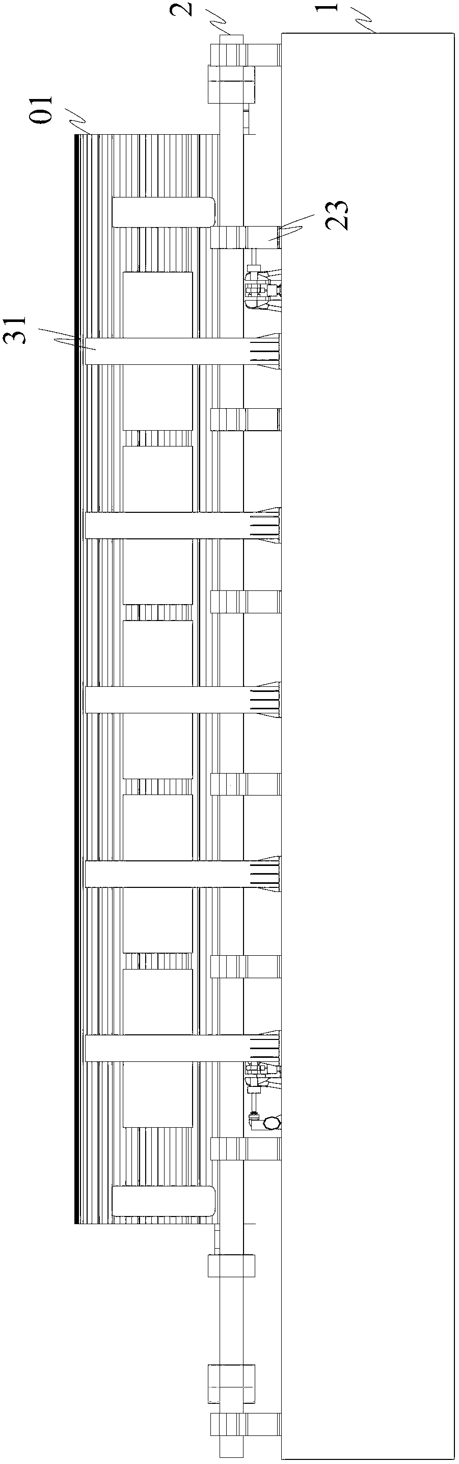
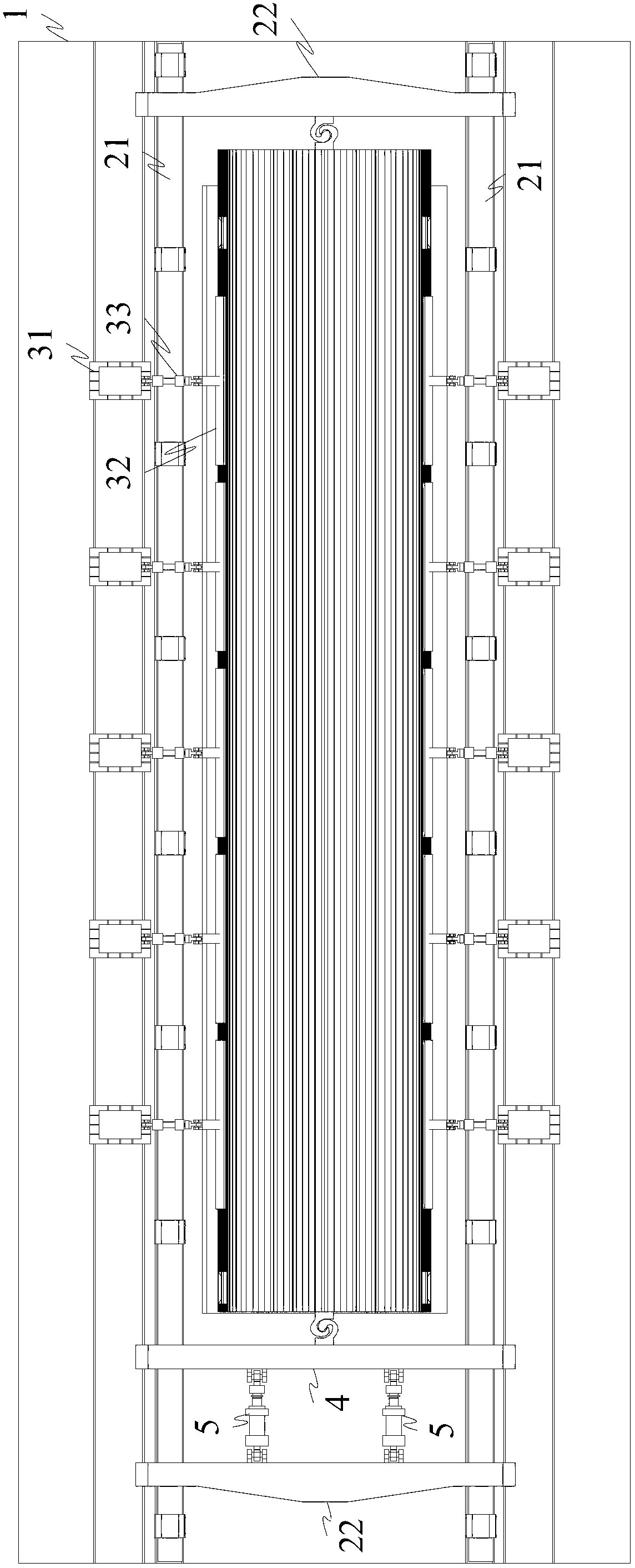
[0016] Such as figure 2 , image 3 As shown, on the basis of Embodiment 1, the above-mentioned test device also has a longitudinal pressing mechanism, and the fixing mechanism 2 specifically adopts a closed ring beam, and the closed ring beam is composed of two longitudinal beams 21 arranged in parallel and two parallel arranged with The reaction beams 22 intersected by the longitudinal beams 21 are enclosed in a closed frame shape. The longitudinal pressing mechanism is specifically a loading beam 4 whose two ends are slidingly connected to the two longitudinal beams respectively. The loading beam 4 and the reaction beam at its proximal end 22 is connected with hydraulic actuator 5. Specifically, the longitudinal beam 21 is fixed on the test bench 1 through a plurality of support seats 23 , and the two ends of the reaction beam 22 are fixedly connected to the two longitudinal beams 21 through fasteners. The hydraulic actuator 5 acts to push or stretch the loading beam 4, t...


PUM


Abstract

The invention provides a simulation test device for a pneumatic load of a vehicle body. The simulation test device is used for a simulation test of the pneumatic load of the vehicle body. The simulation test device consists of a test bed, a fixing mechanism for fixing two ends of the vehicle body to be tested onto the test bed as well as a transverse pressurizing mechanism for applying the pressure on two sides of the vehicle body to be tested, wherein a track for allowing the vehicle body to be tested to move is arranged on the test bed; the transverse pressurizing mechanism comprises a plurality of pressurizing assemblies; each pressurizing assembly consists of an upright post, a wind pressure plate and a hydraulic actuator; the bottom of each upright post is fixedly arranged on the test bed; one end of the hydraulic actuator is hinged with each upright post; and the other end of the hydraulic actuator is hinged with one lateral surface of the wind pressure plate. According to the simulation test device disclosed by the invention, an air pressure load test carried out in the wind pressure plate is replaced by a mechanical device in normal-temperature and normal-pressure environments, and the technical problems that the cost is high and no generality is obtained due to the fact that a pressure container with ultralarge volume is required to be manufactured in the prior art are solved.

Description

technical field [0001] The invention relates to an aerodynamic load simulation test device, which is especially suitable for the aerodynamic load simulation test of a car body of a high-speed EMU. Background technique [0002] With the high speed of railway vehicles, railway vehicles, especially high-speed EMU vehicles, will cause large pressure fluctuations outside the trains when they meet. When trains frequently meet on the line, alternating airtight pressure loads will be formed on the trains. The influence of aerodynamic loads on the strength of EMUs is usually simulated by using an aerodynamic load simulation test device for high-speed EMUs. [0003] The prior art usually adopts a cylindrical tank body, the bottom of which is provided with guide rails, and the car body to be tested is sent into the tank body by means of a process bogie, and then the car body to be tested is sealed in the tank body, and passed to the sealed tank body. Gas is introduced into the body to...

Claims


Application Information

Patent Timeline
IPC IPC(8): G01M17/08
Inventor 王贵国李明高邬平波傅振亮张荧驿于金朋宋烨
Owner CRRC TANGSHAN CO LTD
Features
  • Generate Ideas
  • Intellectual Property
  • Life Sciences
  • Materials
  • Tech Scout
  • Unparalleled Data Quality
  • Higher Quality Content
  • 60% Fewer Hallucinations
Learn More