Ultrasonic flaw detection method

A technology of ultrasonic and flaw detector, which is applied in the direction of using sound wave/ultrasonic wave/infrasonic wave to analyze solids, etc., which can solve the problems of high labor intensity and low work efficiency of inspectors

Inactive Publication Date: 2012-10-03
TAIYUAN IRON & STEEL GROUP
View PDF6 Cites 10 Cited by
  • Summary
  • Abstract
  • Description
  • Claims
  • Application Information

AI Technical Summary

Problems solved by technology

The disadvantages of this operation are: 1. The inspector needs to crouch on the steel plate for a long time during the weld seam inspection. The inspector

Method used


Image

  • Ultrasonic flaw detection method
  • Ultrasonic flaw detection method
  • Ultrasonic flaw detection method

Examples


Embodiment

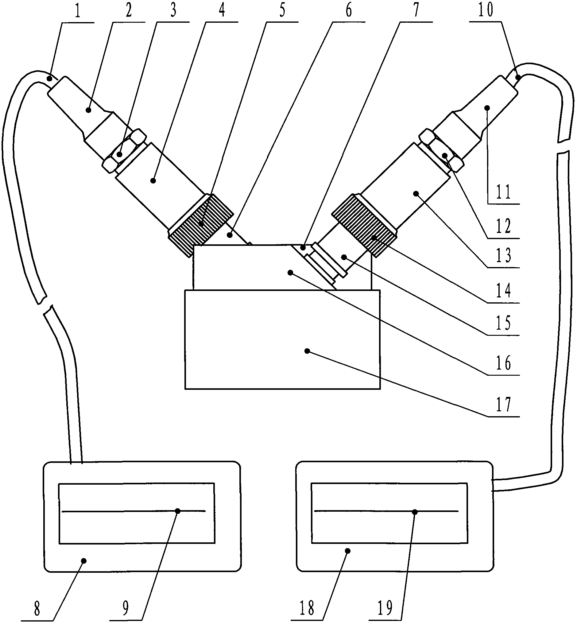
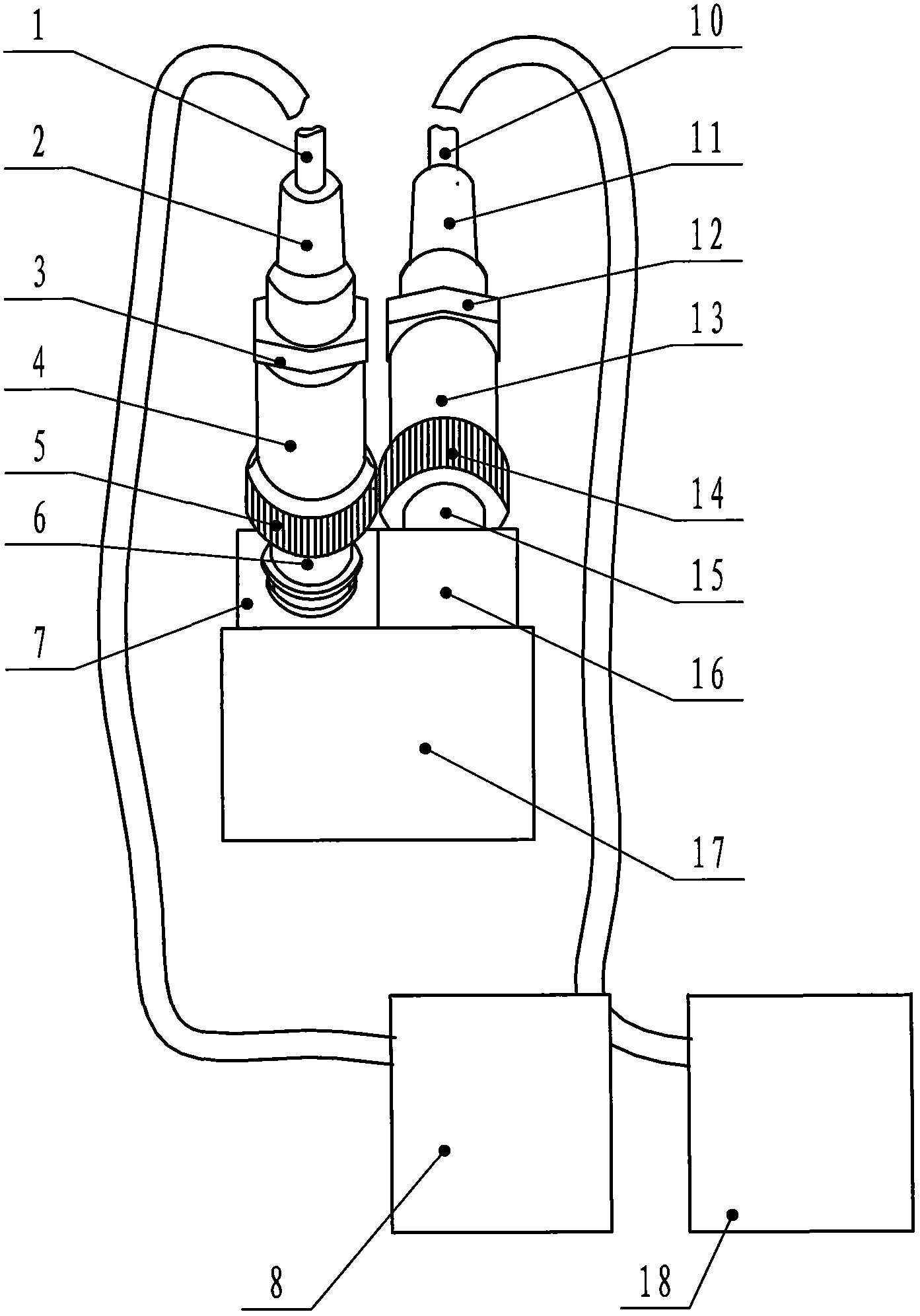
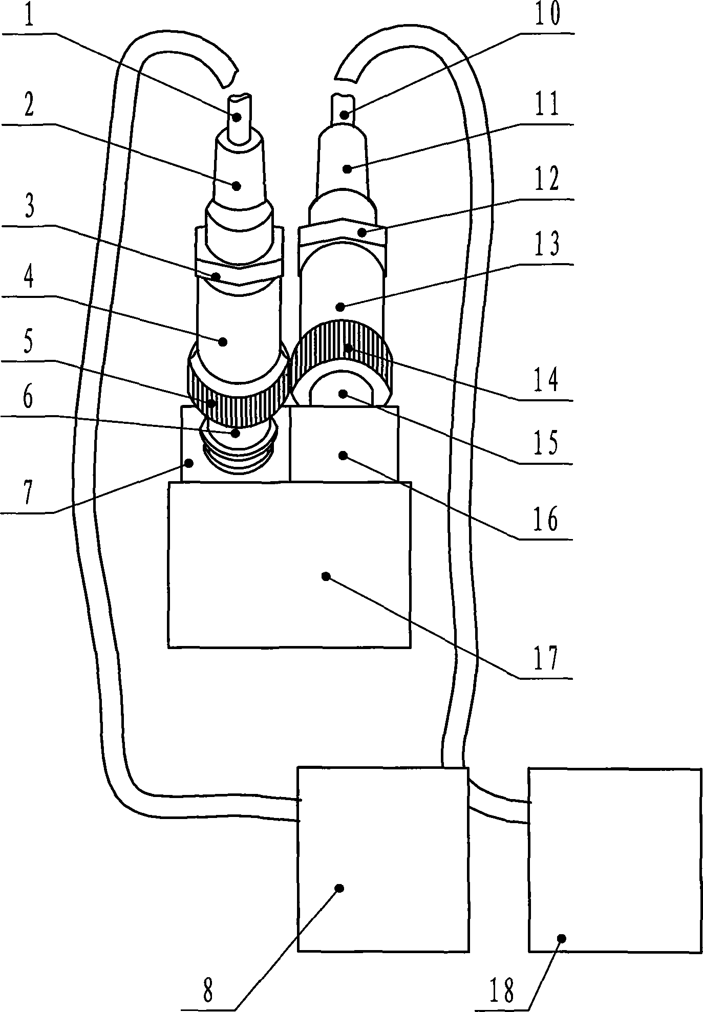
[0024] This embodiment is used to detect butt-welded steel plates with a thickness of 8-120 mm.

[0025] This embodiment is the following sequential steps:

[0026] 1 is according to steel plate thickness 20mm, the ultrasonic probe 7 and the ultrasonic probe 16 of two transverse waves of thickness selection K=2;

[0027] II Connect the ultrasonic probe 7 to the ultrasonic flaw detector 8, and connect the ultrasonic probe 16 to the ultrasonic flaw detector 18; use the test block CSK-I A to measure the actual K values ​​and incident points of the two ultrasonic probes respectively, and the actual value of the ultrasonic probe 7 The K1 value is 1.98, the incident point S1 is 12 mm, the actual K2 value of the ultrasonic probe 16 is 1.99, and the incident point S2 is 12 mm.

[0028] III First place the ultrasonic probe 7 connected to an ultrasonic flaw detector 8 on the test block CSK-III A (short horizontal hole ¢1×6mm contrast test block, thickness 30mm), adjust the gain knob of...


PUM


Abstract

The invention relates to an ultrasonic flaw detection method which comprises the steps as follows: (I) selecting two transverse wave ultrasonic probes with K; (II) respectively connecting the two ultrasonic probes with an ultrasonic flaw detector, and measuring the practical K values and incidence points of the ultrasonic probes with a test block CSK-I A; (III) placing one ultrasonic probe in a test block CSK-III A, adjusting the maximal echo of a phi 1*6 hole with depth of 10 mm to be 80% of reference wave, detecting the holes with depths of 20 mm, 30 mm and 40 mm, connecting the points corresponding to the wave crests to obtain a phi 1*6 distance-amplitude curve, and then increasing by 9 db; (IV) carrying out the operation of the step (III) on the other one ultrasonic probe; (V) fixing the two ultrasonic probes in parallel at oppositely directions; and (VI) carrying out detection by adopting sawtooth type scanning within the range of 2*K*T mm on two sides of welded seam. The ultrasonic flaw detection method can detect the flaws at different directions at one time.

Description

technical field [0001] The invention relates to a method for ultrasonic flaw detection, in particular to a method for ultrasonic flaw detection of steel plates. Background technique [0002] During the excavation and repair process of stainless steel clad plate tailor welding, a certain number of welding defects will be produced, such as air holes, slag inclusions, unfused, incomplete penetration, cracks, etc., among which unfused, incomplete penetration, and cracks all have a certain area. It is more harmful to the steel plate, so it is necessary to detect all these defects as much as possible during the tailor welding inspection, and to ensure the quality of the composite plate through repair welding. Ultrasonic testing requires that the direction of sound wave emission be as perpendicular to the defect as possible, which is conducive to the detection of defects. However, the defects in welded joints are diversified and have different directions. It is necessary to increa...

Claims


Application Information

Patent Timeline
IPC IPC(8): G01N29/04
Inventor 白志伟杨青华
Owner TAIYUAN IRON & STEEL GROUP
Why Eureka
Try Eureka