

Roller brake motor device
A technology of roller brakes and spindles, applied in the direction of electromechanical devices, transmission devices, gear transmission devices, etc., can solve the problems of inconvenient assembly, complex connection structure, bloated internal mechanism of the motor, etc., and achieve convenient connection and assembly, good operation stability, and internal compact effect
- Summary
- Abstract
- Description
- Claims
- Application Information
AI Technical Summary
Problems solved by technology
Method used
Image

Examples
Embodiment
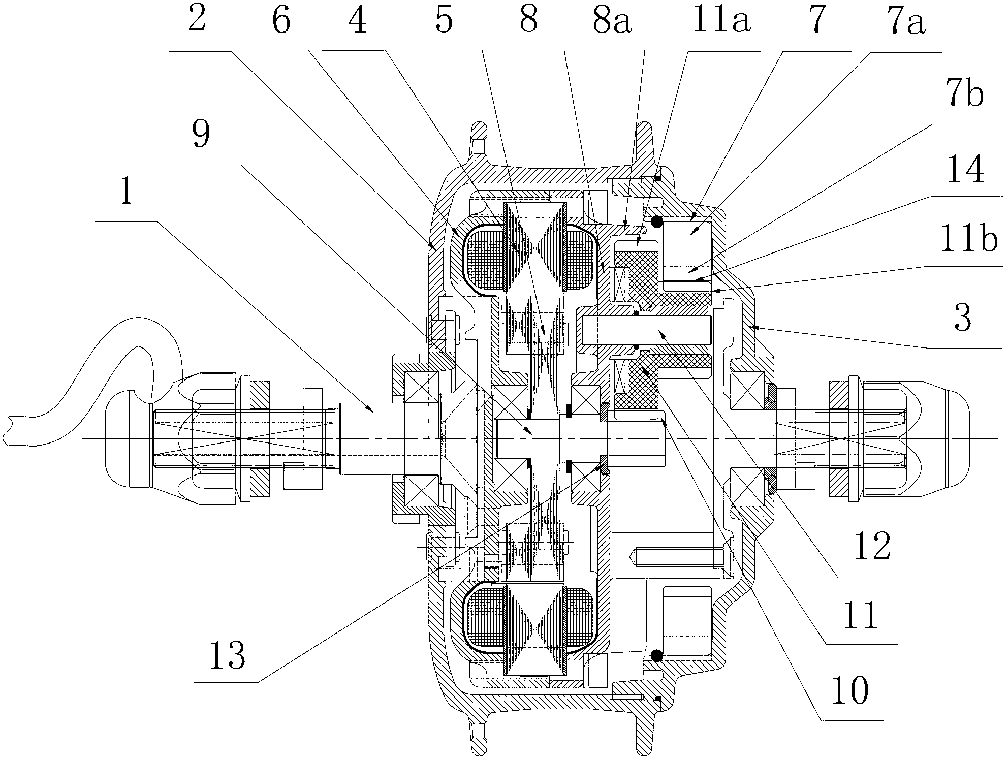
[0019] Example: Combine figure 1 As shown, the roller brake motor device provided by the present invention has a main shaft 1 as in the conventional technology, and a hub shell 2 is installed on the main shaft 1 through a bearing (not shown in the figure), and a hub end is fixed on one side of the hub shell 2 Cover 3, while the hub shell 2 is provided with a stator 4, a rotor 5, a planetary gear reduction mechanism and a clutch 7. The stator 4 is fixed on the stator support 6 , the stator support 6 is fixed on the main shaft 1 , and a gear box cover 8 is fixed on the stator support 6 .
[0020] Specific as figure 1 As shown, in this embodiment, the stator 4 and the rotor 5 adopt an outer stator inner rotor structure, and the planetary gear reduction mechanism consists of a central shaft 9 fixed with the rotor 5, a central shaft gear 10 arranged on the central shaft 9, and a central shaft The three planetary gears 11 meshed with the gear 10 (only one is visible in the f...
PUM
 Abstract
Description
Claims
Application Information