Bogie stop block

A technology of stop blocks and bogies, applied in wheeled and other directions, can solve problems such as damage to stop gaskets, damage to bogie beams or landing gear struts, etc.

Active Publication Date: 2012-10-03
MESSIER DOWTY
View PDF6 Cites 4 Cited by
  • Summary
  • Abstract
  • Description
  • Claims
  • Application Information

AI Technical Summary

Problems solved by technology

Impacts between the stop pads and the landing gear struts with more than a certain amount of energy will cause damage to the stop pads requiring replacement of the stop pads and, in more extreme cases, can cause damage to the bogie beam or landing gear struts. self-inflicted injury

Method used


Image

  • Bogie stop block
  • Bogie stop block
  • Bogie stop block

Examples


Embodiment Construction

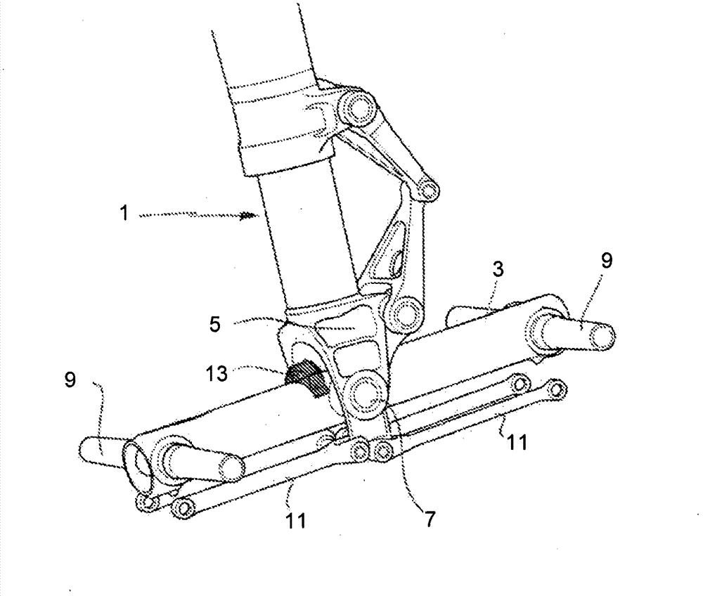
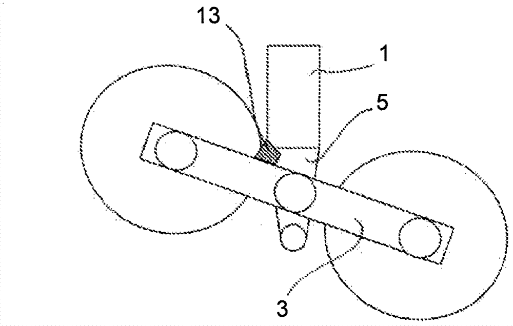
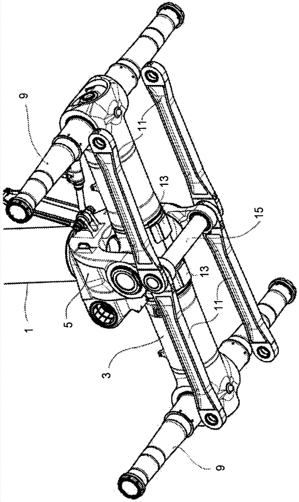
[0027] Referring to FIG. 1 , there is schematically shown an aircraft landing gear assembly known in the prior art. The landing gear comprises a shock strut 1 for aircraft landing gear arranged to be connected to the aircraft at a first upper end and operated in a conventional manner to be stowed or deployed. At the second lower end of the damping strut 1 , the strut is pivotally connected to the bogie beam 3 . A typical arrangement of the lower end of the damping strut 1 includes a fork yoke 5 extending either side and below the bogie beam 3 . A pivot pin 7 pivotally connects the bogie beam 3 to the yoke 5 . The bogie beam usually comprises two or more axles 9 to which the solid aircraft wheels are fixed. Additionally, it is also common practice to provide one or more elongated brake rods 11 extending between the lower extremity of the strut yoke 5 and the brake assembly associated with each aircraft wheel (not shown). Each brake lever 11 is typically pivotally connected t...


PUM


Abstract

An aircraft landing gear assembly including a bogie beam, a landing gear strut (1) having a first end arranged to be pivotally coupled to an aircraft and a second end pivotally coupled to the bogie beam (3), and a stop (13) arranged to limit pivotal movement of the bogie beam relative to the landing gear strut, wherein the stop comprises at least one elongate member arranged to be deflectable in bending when the bogie beam reaches a pivotal limit.

Description

Background technique [0001] A typical arrangement of the main landing gear of medium to large aircraft includes telescoping vibration-damping landing gear struts pivotally connected to a bogie beam mounted with multiple axles and pairs of wheels. In normal operation, there is sufficient clearance between the bottom of the landing gear strut and the bogie beam to allow rotation of the bogie beam relative to the landing gear strut, optionally aided, for example, during takeoff and landing maneuvers and when the landing gear is retracted The landing gear is hidden inside the aircraft. [0002] However, in some cases the bogie beam can be forced to rotate at a higher than normal rotational speed and its inertial fit with the bogie beam can cause a greater than normal rotation angle such that the bogie beam actually hits the landing gear pillar. In order to avoid damage to the bogie beam or landing gear strut in the event of an impact between these bogie beams and struts, it is k...

Claims


Application Information

Patent Timeline
Patent Type & Authority Applications(China)
IPC IPC(8): B64C25/34
CPCB64C25/34
Inventor M・西拉德I・贝内特
Owner MESSIER DOWTY
Why Eureka
Try Eureka