Permanent magnet coupling

A permanent magnet coupler and permanent magnet technology, applied in the direction of permanent magnet clutch/brake, electric brake/clutch, electrical components, etc., can solve the problems of high manufacturing cost and high cost, and achieve low manufacturing cost and no material loss Effect

Inactive Publication Date: 2012-10-03
RINGFEDER POWER TRANSMISSION
View PDF5 Cites 21 Cited by
  • Summary
  • Abstract
  • Description
  • Claims
  • Application Information

AI Technical Summary

Problems solved by technology

Although overall high magnetic flux densities can be obtained with the described permanent magnetic coupler, in which no recirculation elements are necessarily arranged, the production is very complex and expensive, since its shape requires specially adapted magnets

Method used


Image

  • Permanent magnet coupling
  • Permanent magnet coupling
  • Permanent magnet coupling

Examples


Embodiment Construction

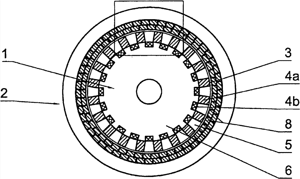
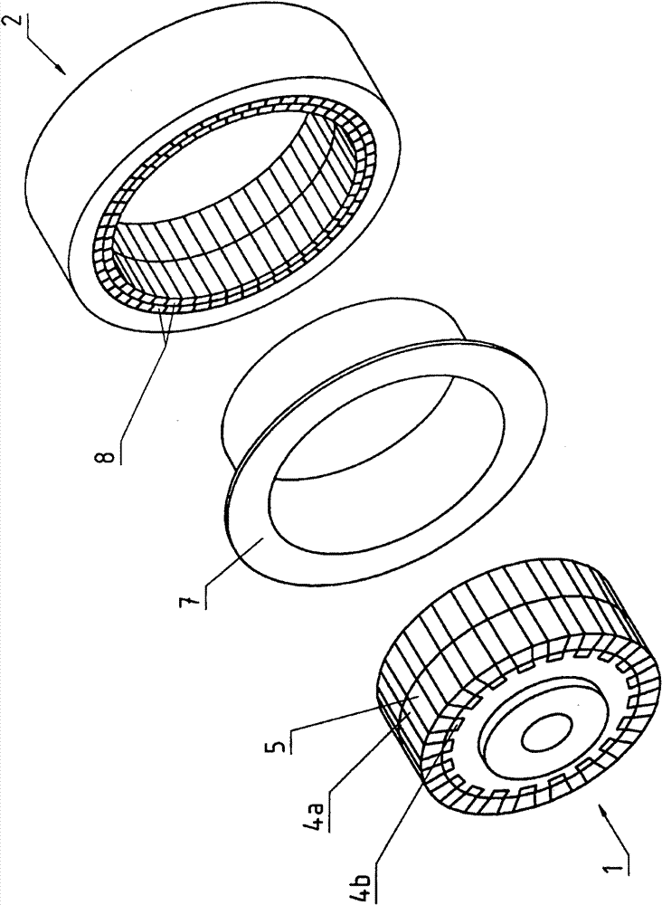
[0023] figure 1 A permanent magnetic coupling for torque transmission is shown with a first component 1 configured as an inner rotor and a second component 2 configured as an outer rotor, which are separated by an air gap 3 . The first component 1 has a first set of permanent magnets 4a and a second set of permanent magnets 4b arranged between these permanent magnets 4a.

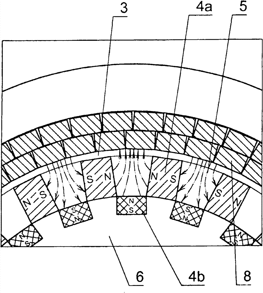
[0024] exist figure 2 It can be seen from the detailed view that the magnetization direction of the first group of permanent magnets 4a is oriented parallel to each adjacent air gap 3 in the circumferential direction, and the permanent magnets 4a of the first group arranged successively in the circumferential direction have alternately opposite the magnetization direction.

[0025] Starting from the air gap 3, the second group of permanent magnets 4b is staggered backward relative to the first group of permanent magnets 4a, so that the gap 5 without permanent magnets is reserved between the air gap 3 and ...


PUM


Abstract

The invention relates to a permanent magnet coupling for the synchronous transmission of torque, comprising a first member (1) having permanent magnets (4a, 4b) and a second member (2), the members being designed as inner rotor and outer rotors and separated by an air gap (3) extending between the members (1, 2), wherein the members (1, 2) are coupled to enable a synchronous movement by forces generated by the permanent magnets (4a, 4b) by the interaction with the second member (2), wherein the first member (1) comprises a first group of permanent magnets (4a) having magnetizing directions parallel to the air gap (3) and a second group of permanent magnets (4b) having magnetizing directions perpendicular to the air gap (3), wherein the permanent magnets (4a, 4b) of the first group and of the second group of the first member (1) are alternately arranged in the circumferential direction, and wherein, as viewed in the circumferential direction, the consecutive permanent magnets (4a) of the first group and the consecutive permanent magnets (4b) of the second group have opposing magnetizing directions, respectively. According to the invention, the permanent magnets (4b) of the second group, starting from the air gap (3), are arranged offset toward the back with respect to the permanent magnet (4a) of the first group such that permanent magnet-free intermediate spaces (5), in particular made of soft iron, remain between the air gap (3) and the permanent magnet (4b) of the second group, said intermediate spaces being delimited laterally by the permanent magnets (4a) of the first group.

Description

technical field [0001] The invention relates to a permanent-magnet coupling for synchronously transmitting torque, comprising a first component with permanent magnets and a second component, the first and second components being configured as an inner rotor and an outer rotor and by The components are separated by an air gap extending between them, the components are coupled so as to be able to move synchronously by the force produced by the interaction of the permanent magnets with the second component, the first component having a first set of permanent magnets with a magnetization direction extending parallel to the air gap The magnets and the second set of permanent magnets have a magnetization direction extending perpendicular to the air gap, and the first set and the second set of permanent magnets of the first member are arranged alternately along the circumferential direction, wherein the first set of successive ones are viewed along the circumferential direction. The ...

Claims


Application Information

Patent Timeline
Patent Type & Authority Applications(China)
IPC IPC(8): H02K49/10
CPCH02K49/106H02K49/102
Inventor T·恩勒特
Owner RINGFEDER POWER TRANSMISSION
Why Eureka
Try Eureka