Parallel type mixing-magnetic-material-based composite-rotor-contained magnetic flux switching motor

A technology of magnetic flux switching motor and composite rotor, which is used in aerospace, wind power generation, electric vehicle, and motor manufacturing fields, can solve the problems of low relative utilization rate of permanent magnets, limited motor application occasions, magnetic saturation of stator teeth, etc. The effect of avoiding magnetic saturation, improving supersaturation and reducing torque ripple

Active Publication Date: 2016-01-27
JIANGSU UNIV
View PDF6 Cites 8 Cited by
  • Summary
  • Abstract
  • Description
  • Claims
  • Application Information

AI Technical Summary

Problems solved by technology

Chinese patent No. 201410508547.2 proposes a flux switching motor using hybrid permanent magnets. The motor installs a high energy product rare earth permanent magnet on the yoke of the stator module of the flux switching permanent magnet motor. Ferrite permanent magnets with low magnetic energy product are installed on the teeth of the stator module, thus forming a hybrid permanent magnet module in which rare earth permanent magnets are connected with ferrites, which overcomes the high cost of the existing flux switching motors and serious stator teeth. The problem of magnetic saturation
However, this motor still cannot solve the problem of severe magnetic flux leakage outside the stator, resulting in a relatively low utilization rate of the permanent magnets, which limits the application of the motor to a certain extent.

Method used


Image

  • Parallel type mixing-magnetic-material-based composite-rotor-contained magnetic flux switching motor
  • Parallel type mixing-magnetic-material-based composite-rotor-contained magnetic flux switching motor
  • Parallel type mixing-magnetic-material-based composite-rotor-contained magnetic flux switching motor

Examples


Embodiment Construction

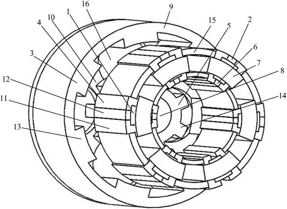
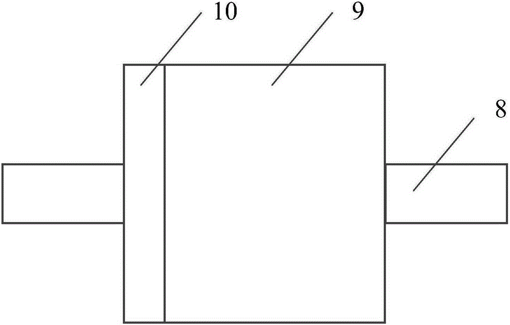
[0033] see figure 1 and figure 2 , the present invention consists of an outer rotor 3, a stator 4, an inner rotor 5, an armature winding 7 and a non-magnetic rotating shaft 8. The outer rotor 3 is coaxial with an empty stator 4 , the stator 4 is coaxial with an inner rotor 5 , and the inner rotor 5 is coaxially fixed on a non-magnetic rotating shaft 8 . An annular disc 10 is fixedly installed on the same axial end surface of the outer rotor 3 and the inner rotor 5, and the outer rotor 3 and the inner rotor 5 are fixedly connected together through the annular disc 10, and the connection method is riveting or welding, so that the outer rotor 3. The inner rotor 5 and the annular disk 10 form a compound rotor 9, which is an integral structure, and the stator 4, the compound rotor 9 and the non-magnetic rotating shaft 8 belong to a concentric and coaxial collar structure as a whole. In this way, the present invention sequentially includes the non-magnetic rotating shaft 8, the i...


PUM


Abstract

The invention discloses a parallel type mixing-magnetic-material-based composite-rotor-contained magnetic flux switching motor. A non-magnetic-conductive rotating shaft, an inner rotor, a stator, and an outer rotor are installed successively and concentrically from inside to outside at a radial direction in a sleeving mode. The stator contains stator iron cores, mixed permanent magnet modules and three-phase armature windings; the three-phase armature windings are arranged between the adjacent stator iron cores; one mixed permanent magnet module is embedded into the middle of each stator iron core tightly and fixedly; and each mixed permanent magnet module is formed by seamless connection of an internal neodymium iron boron permanent magnet, a ferrite permanent magnet, and an external neodymium iron boron permanent magnet from inside to outside along the radial direction. On the basis of the stator-free yoke-type structural design, obvious series magnetic circuits of the adjacent permanent magnets are formed on the magnetic flux paths by combining the composite rotor, thereby avoiding a phenomenon of supersaturation of the stator tooth part and effectively improving the utilization rate of the permanent magnet. The stator tooth employs a non-equal-arc design, so that the total positioning moment on the composite rotor is reduced and thus an effect of reduction of torque pulsation is realized.

Description

technical field [0001] The invention belongs to the technical field of motor manufacturing, in particular to a flux-switching motor of mixed magnetic material with the characteristics of relatively high power density, high torque density, high efficiency, etc., which is applied in the fields of aerospace, wind power generation, electric vehicles and the like. Background technique [0002] With the soaring price of rare earth permanent magnet materials, the manufacturing cost of rare earth permanent magnet motors has also increased year by year, so rare earth motors and non-rare earth motors have appeared. There are two main ways to reduce the amount of rare earth permanent magnet materials. One is to use mixed excitation. The permanent magnet generates the main magnetic flux, and the electric excitation generates the auxiliary magnetic flux. The interaction between them realizes the conversion of electromagnetic energy, making the hybrid excitation motor While reducing the a...

Claims


Application Information

Patent Timeline
Patent Type & Authority Applications(China)
IPC IPC(8): H02K16/02H02K1/17H02K29/03
Inventor 朱孝勇樊德阳全力杜怿
Owner JIANGSU UNIV
Why Eureka
Try Eureka