

Relay device and relay method
A relay device and a specific technology, applied in radio relay systems, active electrical relay systems, radio transmission systems, etc., to achieve the effect of improving error rate characteristics and reducing delay
- Summary
- Abstract
- Description
- Claims
- Application Information
AI Technical Summary
Problems solved by technology
Method used
Image

Examples
Embodiment approach 1
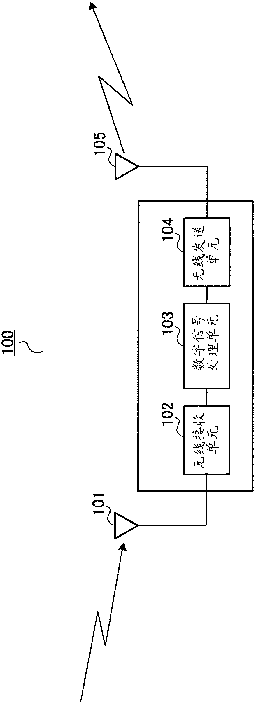
[0040] figure 1 It is a block diagram showing the configuration of the relay device 100 according to Embodiment 1 of the present invention.
[0041] The relay device 100 mainly includes: an antenna 101 , a wireless receiving unit 102 , a digital signal processing unit 103 , a wireless sending unit 104 and an antenna 105 . Each structure will be described in detail below.
[0042] Antenna 101 receives a signal from a base station (not shown), and outputs it to radio receiving section 102 .
[0043] Radio receiving section 102 converts a signal input from antenna 101 from a radio frequency to a baseband frequency, and outputs it to digital signal processing section 103 .
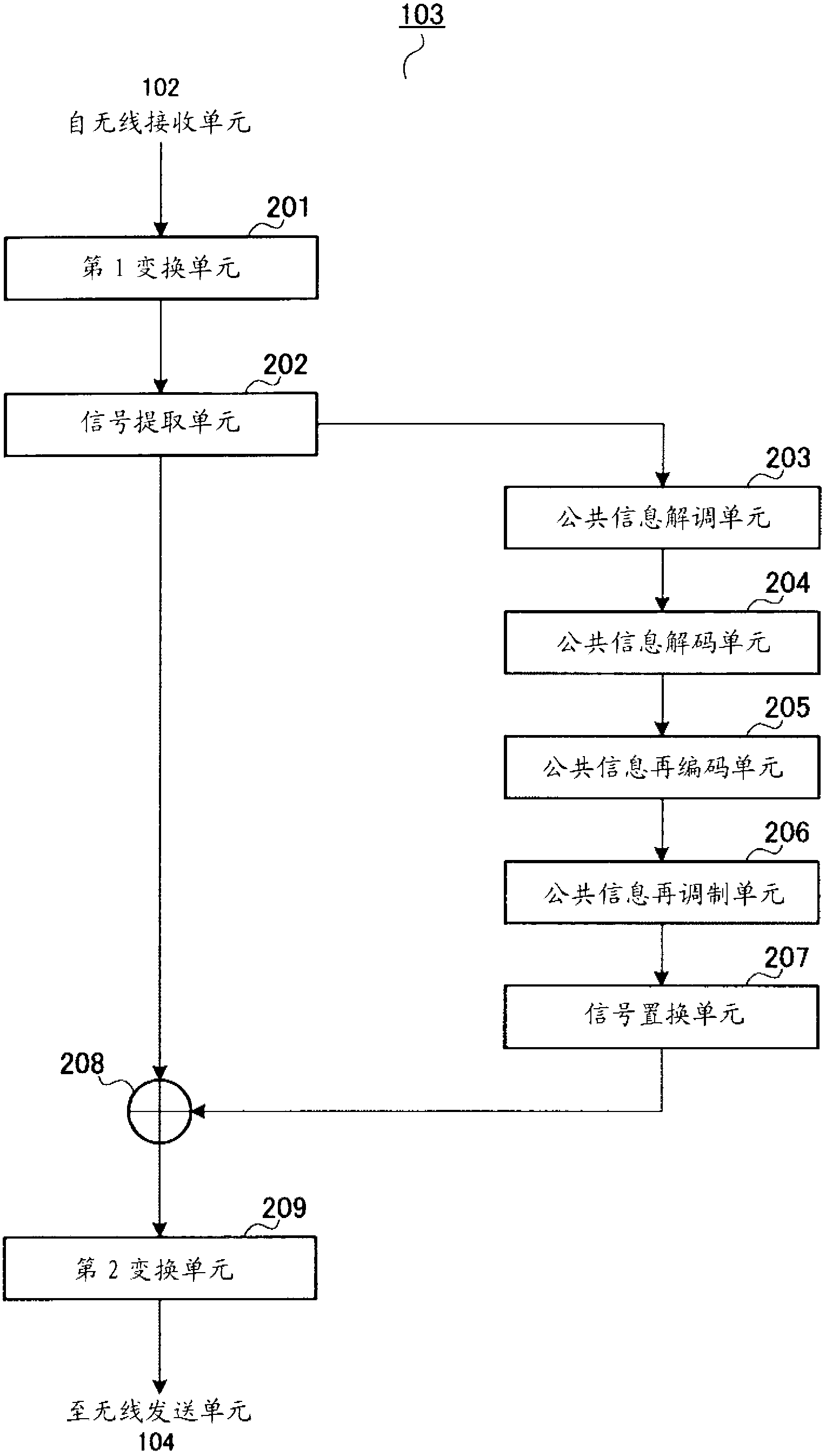
[0044] Digital signal processing section 103 performs digital signal processing on the signal input from wireless receiving section 102 and outputs it to wireless transmitting section 104 . In addition, details of the configuration and processing of the digital signal processing unit 103 will be described l...
Embodiment approach 2
[0069] Figure 4 It is a block diagram showing the configuration of the digital signal processing unit 400 according to Embodiment 2 of the present invention. In addition, in this embodiment, for the structure of the relay device, except for the figure 1 Except that the digital signal processing unit 400 is provided instead of the digital signal processing unit 103, the other parts are the same as figure 1 are the same, so its description is omitted. In addition, in this embodiment, for structures other than the digital signal processing unit 400 of the relay device, use figure 1 label.
[0070] The digital signal processing unit 400 mainly includes: a P-SS detection unit 401 , a P-SS generation unit 402 , a signal replacement unit 403 , a first transformation unit 404 , a signal extraction unit 405 , an addition unit 406 and a second transformation unit 407 . Each structure will be described in detail below.
[0071] P-SS detection section 401 detects a primary synchroni...
Embodiment approach 3
[0083] Figure 5 It is a block diagram showing the configuration of digital signal processing unit 500 according to Embodiment 3 of the present invention. In addition, in this embodiment, for the structure of the relay device, except for the figure 1 Except that the digital signal processing unit 500 is provided instead of the digital signal processing unit 103, the other parts are the same as figure 1are the same, so its description is omitted. In addition, in the description of this embodiment, the configuration other than the digital signal processing unit 500 of the relay device is used figure 1 label.
[0084] The digital signal processing unit 500 mainly includes: a first transformation unit 501 , a signal extraction unit 502 , an S-SS detection unit 503 , an S-SS generation unit 504 , a signal replacement unit 505 , an addition unit 506 and a second transformation unit 507 . Each structure will be described in detail below.
[0085] The first transformation section...
PUM
 Abstract
Description
Claims
Application Information