Check patentability & draft patents in minutes with Patsnap Eureka AI!

OFDM transmitting / receiving device and method

A technology of receiving device and receiving power, applied in the directions of separation device of transmission path, power management, orthogonal multiplexing system, etc., can solve the problems of inconsistent received power and deterioration of error rate characteristics, etc.

Inactive Publication Date: 2001-03-14
PANASONIC INTELLECTUAL PROPERTY CORP OF AMERICA
View PDF2 Cites 4 Cited by
  • Summary
  • Abstract
  • Description
  • Claims
  • Application Information

AI Technical Summary

Problems solved by technology

[0009] Because the received power of the existing OFDM transmitting and receiving device is not constant, the errors are concentrated on the subcarriers where the receiving power drops suddenly, and the error rate characteristic is deteriorated

Method used


Image

  • OFDM transmitting / receiving device and method
  • OFDM transmitting / receiving device and method
  • OFDM transmitting / receiving device and method

Examples


Embodiment 1

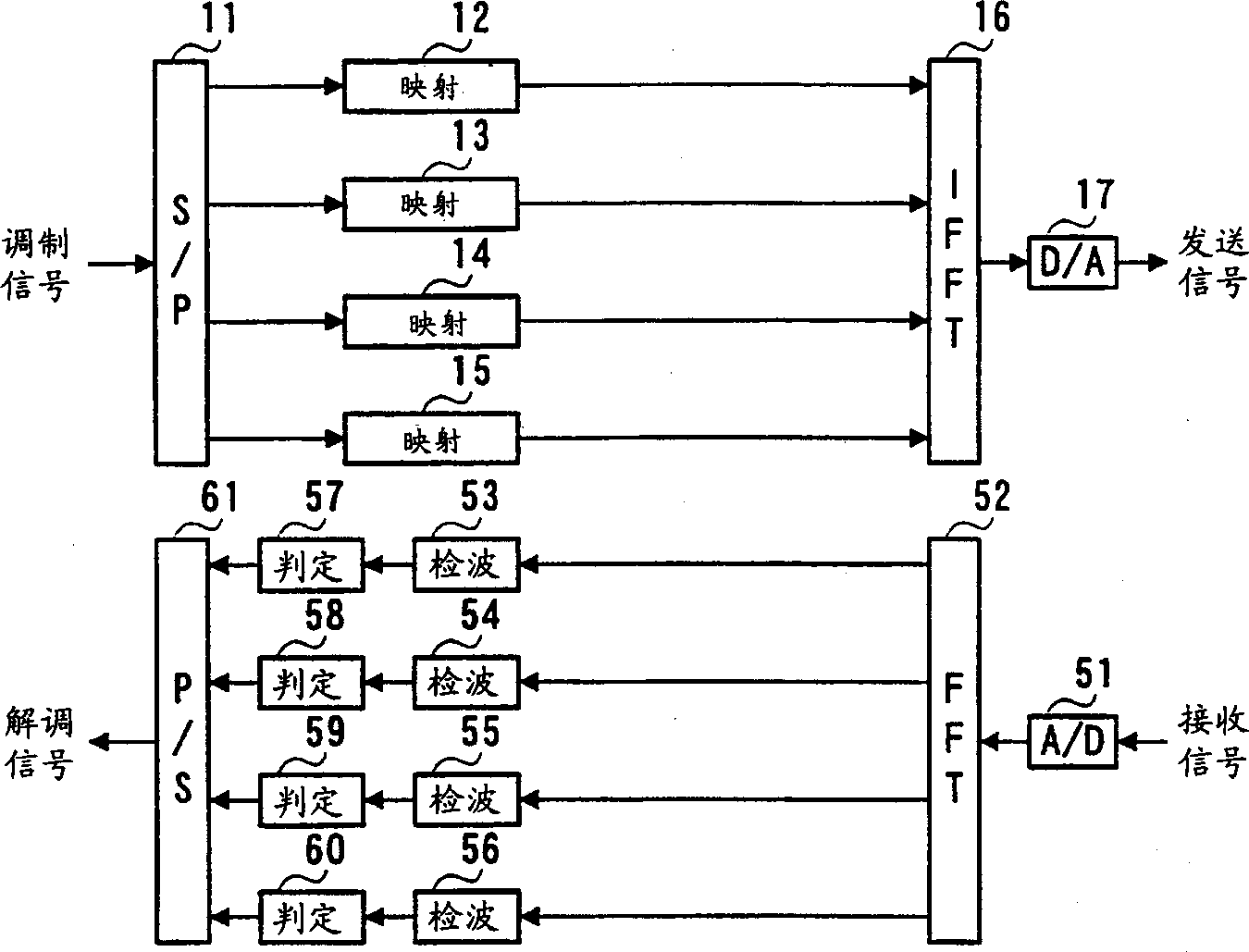
[0046] image 3 It is a structural block diagram of the OFDM transmitting and receiving device according to Embodiment 1 of the present invention. exist image 3 Among them, the S / P (Serial-Parallel) conversion circuit 101 converts a primary modulated transmission signal of one sequence into signals of a plurality of sequences. In this embodiment, one sequence of signals is converted into four sequences of signals.

[0047] Mapping circuits 102 to 105 map the S / P converted subcarriers A to D signals, respectively. Multipliers 106 to 109 multiply the mapped subcarriers A to D signals by predetermined coefficient signals (hereinafter, referred to as "coefficient signals").

[0048] An IFFT (Inverse Fast Fourier Transform) circuit 110 performs inverse fast Fourier transform on the transmission signals output from the multipliers 106-109. The D / A (Digital / Analog) conversion circuit 111 performs D / A conversion on the output signal of the IFFT circuit 110 to output a transmissio...

Embodiment 2

[0069] Figure 6 It is a block diagram showing the structure of the control circuit 162 of the OFDM transmitting and receiving device according to Embodiment 2 of the present invention. exist Figure 6 In the OFDM sending and receiving device shown, for Figure 4 The common part of the OFDM sending and receiving device shown is attached with Figure 4 The same reference numerals are used, and descriptions thereof are omitted.

[0070] Figure 6 The OFDM sending and receiving device shown is the same as Figure 4 Compared with the conventional OFDM transmission / reception apparatus, connection switches 221 to 224 are added in the control circuit 162 .

[0071] The envelope generators 201 to 204 output the generated envelopes to the connection switches 221 to 224 . Connection switches 221-224 output only the final symbols of the signals of subcarriers A-D output from envelope generators 201-204 to averaging circuit 205 and dividers 206-209 based on timing signals.

[0072]...

Embodiment 3

[0075] Figure 7 It is a block diagram showing the structure of the control circuit 162 of the OFDM transmitting and receiving device according to Embodiment 3 of the present invention. exist Figure 7 In the OFDM sending and receiving device shown, for Figure 4 The common part of the OFDM sending and receiving device shown is attached with Figure 4 The same reference numerals are used, and descriptions thereof are omitted.

[0076] Figure 7 The OFDM sending and receiving device shown is the same as Figure 4 Averaging circuits 231 to 234 are added in the control circuit 162 compared to the conventional OFDM transmitting and receiving device.

[0077] The envelope generators 201 to 204 output the generated envelopes to the averaging circuits 231 to 234 . Averaging circuits 231 to 234 calculate average values ​​of signals of respective subcarriers A to D output from envelope generators 201 to 204 based on timing signals, and output them to averaging circuit 205 and div...


PUM


Abstract

An average value of reception power of subcarriers A to D is calculated by a control circuit 162, and the average value is divided by envelops of received signals of subcarriers A to D, respectively, so as to calculate a coefficient signal of each subcarrier. Multipliers 106 to 109 multiply transmitting signals of subcarriers A to D output from mapping circuits 102 to 105 by the coefficient signals, respectively. Whereby, power between the subcarriers at a reception time can be maintained substantially constant so as to improve an error rate characteristic.

Description

technical field [0001] The present invention relates to an OFDM transmitting and receiving device and an OFDM transmitting and receiving method used in communication equipment of a digital wireless communication system adopting the OFDM method. Background technique [0002] In recent years, OFDM (Orthogonal Frequency Division Multiplexing: Orthogonal Frequency Division Multiplexing) method is being studied in digital wireless communication systems. It is a kind of multi-carrier digital modulation method and has strong resistance to noise and multipath interference. [0003] Hereinafter, signal processing of a conventional OFDM transmission / reception apparatus will be described with reference to the drawings. figure 1 It is a structural block diagram of an existing OFDM transmitting and receiving device. suppose figure 1 The number of subcarriers in is 4. [0004] First, at the transmitting end, the primary modulated transmission signal is parallel-converted into the numbe...

Claims


Application Information

Patent Timeline
Patent Type & Authority Applications(China)
IPC IPC(8): H04B1/04H04J11/00H04B7/005H04B7/26H04L27/26
CPCH04L5/0007H04L27/2637H04L5/0046H04L27/2646H04W52/346H04L27/2614H04L27/2653H04W52/42H04L27/26
Inventor 须藤浩章石川公彦
Owner PANASONIC INTELLECTUAL PROPERTY CORP OF AMERICA
Features
  • R&D
  • Intellectual Property
  • Life Sciences
  • Materials
  • Tech Scout
  • Unparalleled Data Quality
  • Higher Quality Content
  • 60% Fewer Hallucinations
Learn More