Check patentability & draft patents in minutes with Patsnap Eureka AI!

Receiving device and transmitting device

A technology of a transmitting device and a receiving device, which is applied in the directions of preventing/detecting errors through diversity reception, space transmit diversity, and communication between multiple stations, and can solve problems such as inability to use at the same time, inability to receive sequences in parallel and alternate, etc.

Inactive Publication Date: 2002-12-04
PANASONIC CORP
View PDF1 Cites 5 Cited by
  • Summary
  • Abstract
  • Description
  • Claims
  • Application Information

AI Technical Summary

Problems solved by technology

However, UDMV constructs a virtual encoder obtained by fusing an equalizer and a convolutional encoder. Equalization and error correction are performed simultaneously in this virtual encoder. Therefore, parallel alternation of received sequences cannot be performed between equalization and error correction. Simultaneous use of interleaving and UDMV

Method used


Image

  • Receiving device and transmitting device
  • Receiving device and transmitting device
  • Receiving device and transmitting device

Examples


Embodiment 1

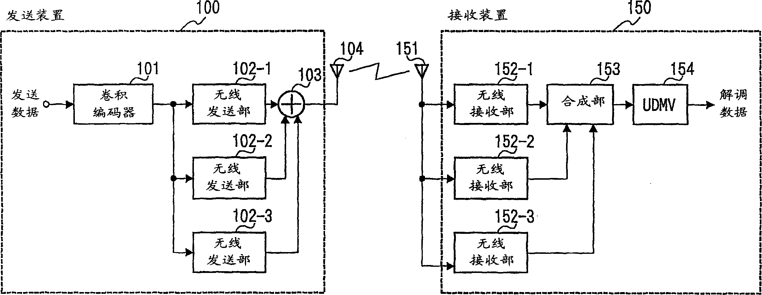
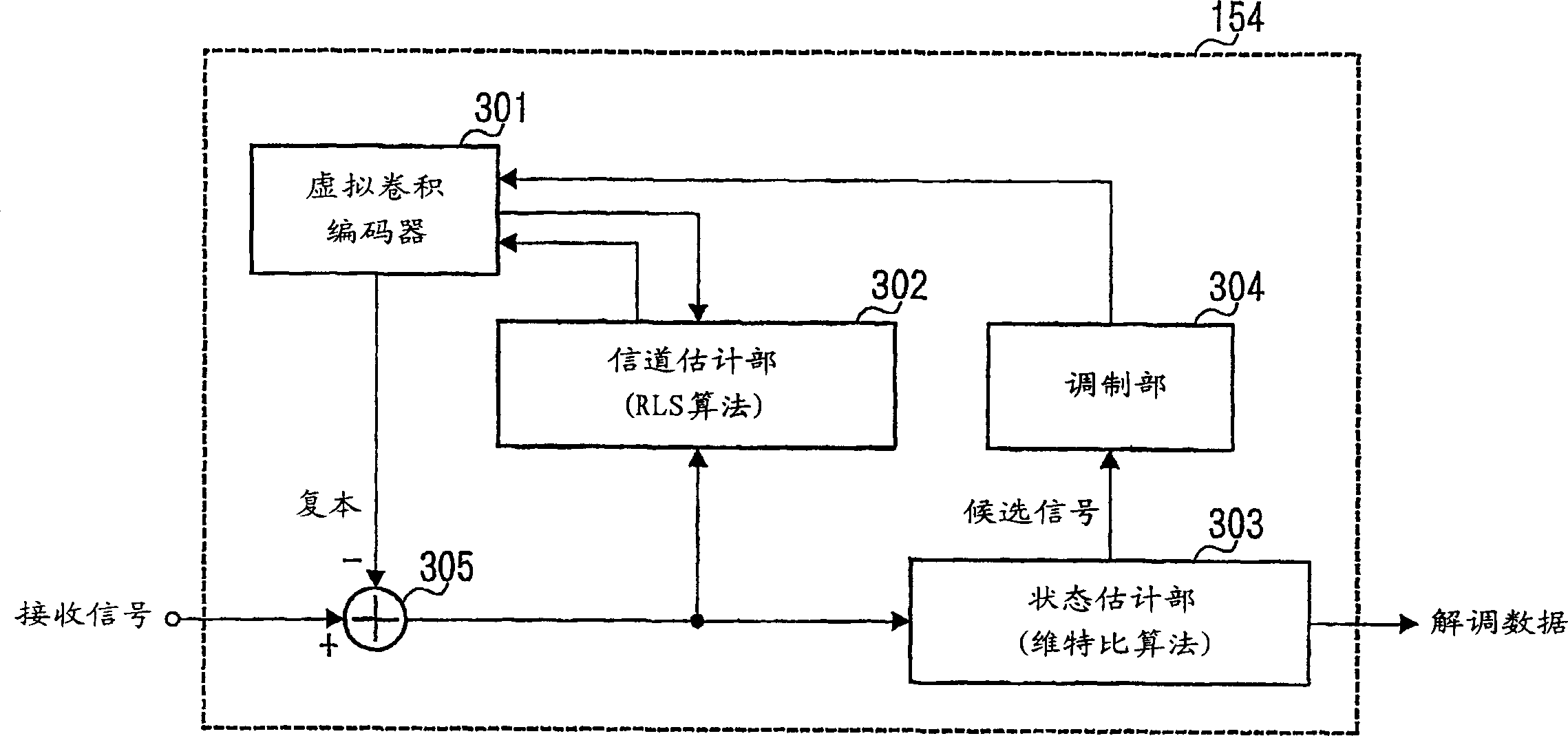
[0029] This embodiment is an example of frequency diversity. The transmitting end allocates the transmission data to multiple carriers with different frequencies and transmits them, while the receiving end performs maximum ratio combination and compensation for the received signals subjected to different fading in the line to form a burst error. An example of demodulating a signal obtained by compensating for the signal distortion caused by fading using UDMV for signal distortion caused by fading which is the main factor.

[0030] figure 1 A block diagram showing a schematic configuration of a receiving device and a transmitting device according to Embodiment 1 of the present invention.

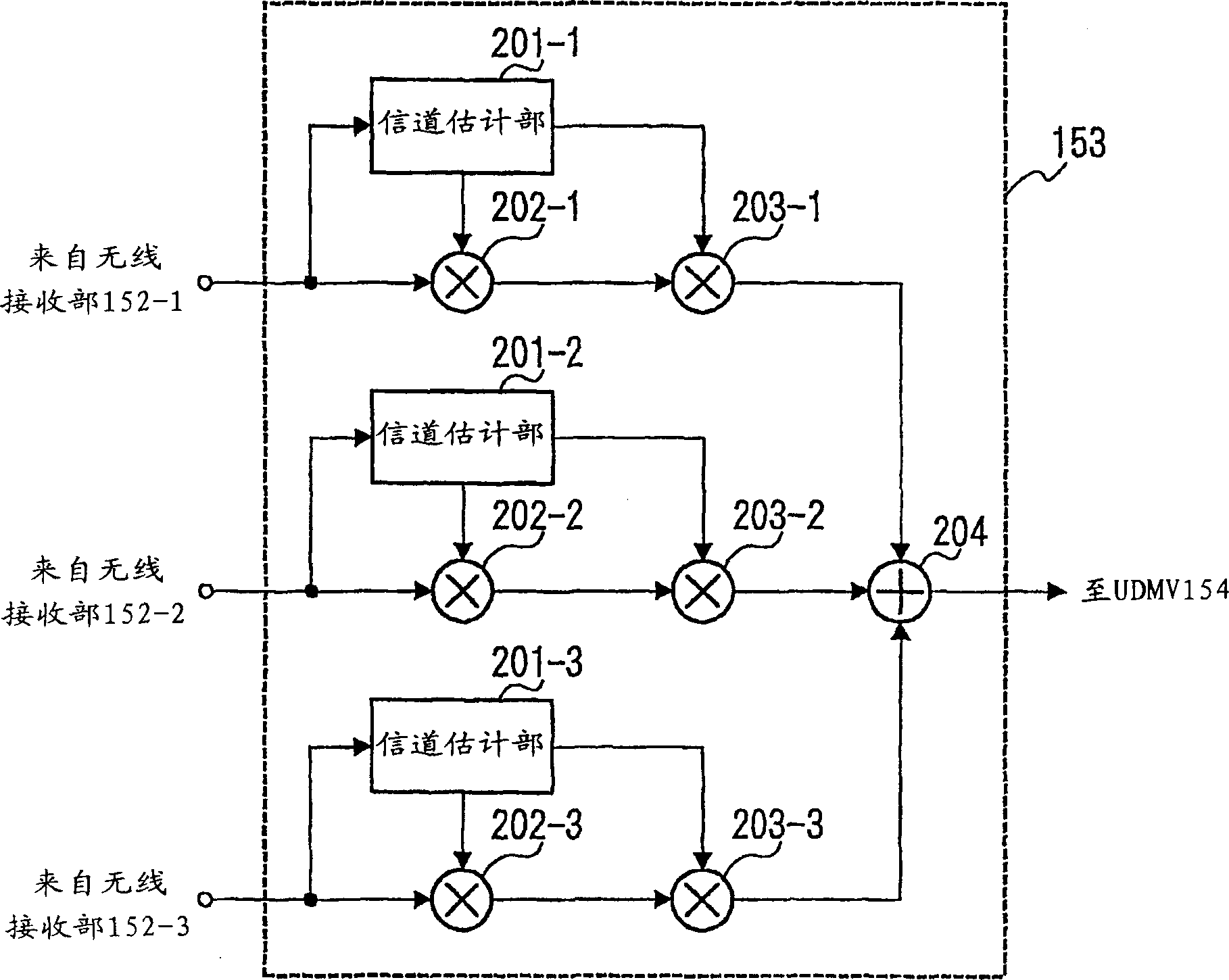
[0031] The transmission device 100 of the present embodiment allocates transmission data to a plurality of carriers of different frequencies, and transmits in a plurality of sequences separated by frequencies. The receiving device 150 performs maximum-ratio combination on the received signal...

Embodiment 2

[0057] In this embodiment, at the transmitting end, the transmission data converted into parallel signals is distributed to multiple carriers with different frequencies and transmitted, and the received signals (parallel signals) subjected to different fading in the line are converted into serial signals at the receiving end, To compensate the burst error, use UDMV to demodulate the signal with the burst error compensated.

[0058] Figure 5 A block diagram showing a schematic configuration of a receiving device and a transmitting device according to Embodiment 2 of the present invention.

[0059] The transmission device 400 of this embodiment multiplies the transmission data converted into a parallel signal by a plurality of carriers of different frequencies, and transmits the data. The receiving device 405 converts the received signal into a serial signal, performs equalization and Viterbi decoding simultaneously by UDMV, and obtains received data.

[0060] First, the conf...

Embodiment 3

[0071] This embodiment is a modified example of Embodiment 1, and the difference from Embodiment 1 is that the transmitted signal is subjected to spread spectrum processing and then multiplied by a carrier. Below, refer to Figure 7 This embodiment will be described. The same reference numerals as in Embodiment 1 are assigned to the same parts as in Embodiment 1, and explanations thereof are omitted.

[0072] Figure 7 A block diagram showing a schematic configuration of a receiving device and a transmitting device according to Embodiment 3 of the present invention. Although omitted in the figure, it is assumed that the receiving device 550-B and the receiving device 550-C have the same configuration as the receiving device 550-A.

[0073] The transmitting device 500 performs wireless communication with the receiving devices 550-A to 550-C. In the transmission device 500, the convolutional encoders 101-A to 101-C perform convolutional coding on the corresponding transmissi...


PUM


Abstract

A receiving device and a transmitting device capable of improving the error rate characteristics of demodulated data by correcting burst errors even when fading caused by burst errors exists on a line, including simultaneous equalization and Receiving means of the demodulator for error correction and transmitting means for transmitting data to the receiving means. The transmitting device 100 allocates transmission data to a plurality of carriers of different frequencies, and transmits in a plurality of sequences separated by frequencies. The receiving device 150 performs maximum ratio combining on the received signal in the combining unit 153, and simultaneously performs equalization and Viterbi decoding by UDMV154 to obtain demodulated data.

Description

technical field [0001] The present invention relates to a receiving device for compensating and correcting signal distortion caused by multipath fading and a transmitting device for transmitting data to the receiving device. Background technique [0002] In the field of mobile communication, it is essential to overcome multipath fading and improve transmission quality. An equalizer is effective for overcoming multipath fading, and an error correction code method, especially a method of decoding a convolutional code with a Viterbi decoder is effective for improving transmission quality. [0003] The existing receiving device and transmitting device (hereinafter, they are referred to as "transmission device" for short) use MLSE (Maximum Likelihood Sequence Estimator; Maximum Likelihood Sequence Estimator) or DFE (Decision Feedback Equalizer; Decision Feedback Equalizer) to equalize The device is used to compensate the signal distortion caused by multi...

Claims


Application Information

Patent Timeline
Patent Type & Authority Applications(China)
IPC IPC(8): H03M13/41H04B7/005H04B7/06H04B7/08H04B7/26H04L1/00
CPCH04L1/0054H04L1/04H04L25/0224H04L25/03286H04B7/005
Inventor 上杉充
Owner PANASONIC CORP
Features
  • R&D
  • Intellectual Property
  • Life Sciences
  • Materials
  • Tech Scout
  • Unparalleled Data Quality
  • Higher Quality Content
  • 60% Fewer Hallucinations
Learn More