
Power off memory circuit and power off memory method for full-automatic impeller type washing machine
A pulsator washing machine and power-off memory technology, which is applied to other washing machines, control devices of washing machines, washing devices, etc., can solve problems such as inability to continue to execute, and achieve the effect of more functions, humanized functions, and improved intelligence.
- Summary
- Abstract
- Description
- Claims
- Application Information
AI Technical Summary
Problems solved by technology
Method used
Image

Examples
Embodiment Construction
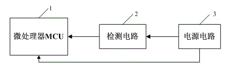
[0015] A power-off memory circuit for a full-automatic pulsator washing machine, comprising a microcontroller MCU 1, the input end of which is connected to the output end of a detection circuit 2, a power supply circuit 3 supplies power to the detection circuit 2 and the microcontroller MCU 1, and the microcontroller MCU 1 Built-in FLASH memory, such as figure 1 shown.
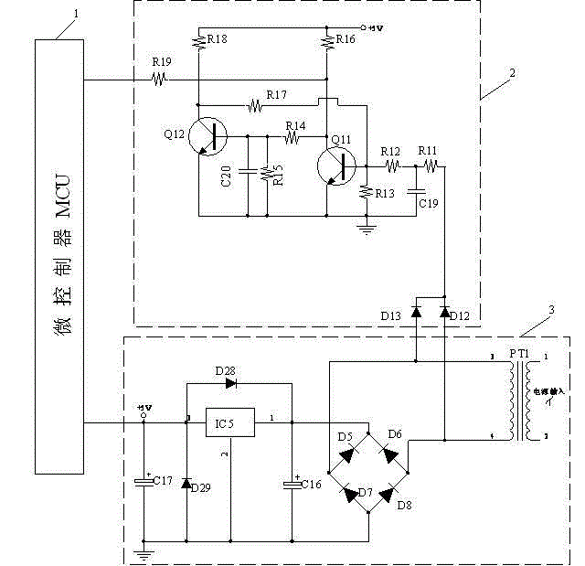
[0016] Such as figure 2 As shown, the power supply circuit 3 includes a transformer PT1 whose input terminal is connected to 220V alternating current. The output terminals of the transformer PT1 are respectively connected to the detection circuit 2 and the input terminals of the rectifier bridge. The rectifier bridge is composed of diodes D5, D6, D7, and D8. The full-wave rectifier bridge, the crystal capacitor C16 is connected to the output end of the rectifier bridge in parallel, one end of the crystal capacitor C16 is grounded, and the other end is connected to the input end of the microcontroller MCU 1 t...
PUM
 Abstract
Description
Claims
Application Information