Method and device for generating kinetic energy and refrigerating

A kinetic energy and equipment technology, applied in lighting and heating equipment, refrigerators, mechanical equipment, etc., can solve the problems of not being able to provide a cold source, and not being able to convert heat energy into kinetic energy

Active Publication Date: 2012-10-10
王法文
View PDF5 Cites 0 Cited by
  • Summary
  • Abstract
  • Description
  • Claims
  • Application Information

AI Technical Summary

Problems solved by technology

[0003] The present invention uses the main heat exchanger (4) to allow the liquid working medium pumped out by the working medium pump (5) to only absorb the gas that flows out from the outlet of the expander (1) described in the above-mentioned patent and passes through the heat exchanger. (2) The gaseous working medium entering the compressor (3) generates compression heat due to being compressed by the compressor (3), thereby providing a method and equipment for generating kinetic energy and refrigeration, and solving the problem of making the normal temperature heat source The stored heat energy cannot be converted into kinetic energy and cannot provide a cold source

Method used


Image

  • Method and device for generating kinetic energy and refrigerating
  • Method and device for generating kinetic energy and refrigerating
  • Method and device for generating kinetic energy and refrigerating

Examples


Embodiment 1

[0043] A kind of method for generating kinetic energy and refrigeration, its technical scheme has 11 implementation steps altogether, and its implementation steps are:

[0044] [1] Let the non-condensable gas suction pump (5) pump out the non-condensable gas that needs to be pumped out in the pipeline of the work cycle and the equipment;

[0045] [2] Let the liquid working medium in the evaporator (7) which has a boiling point lower than normal temperature and has no superfluidity when it is in the liquid phase absorb heat from the heat source and heat up;

[0046] [3] Let the work medium in the evaporator (7) that has exchanged heat with the heat source to heat up enter the expander (1) connected to it to do work;

[0047] [4] Let the gaseous working medium flowing out from the outlet of the expander (1) after doing work enter the chamber A of the heat exchanger (2) and then enter the compressor (3);

[0048] [5] Let the compressor (3) compress and heat up the gaseous workin...

Embodiment 2

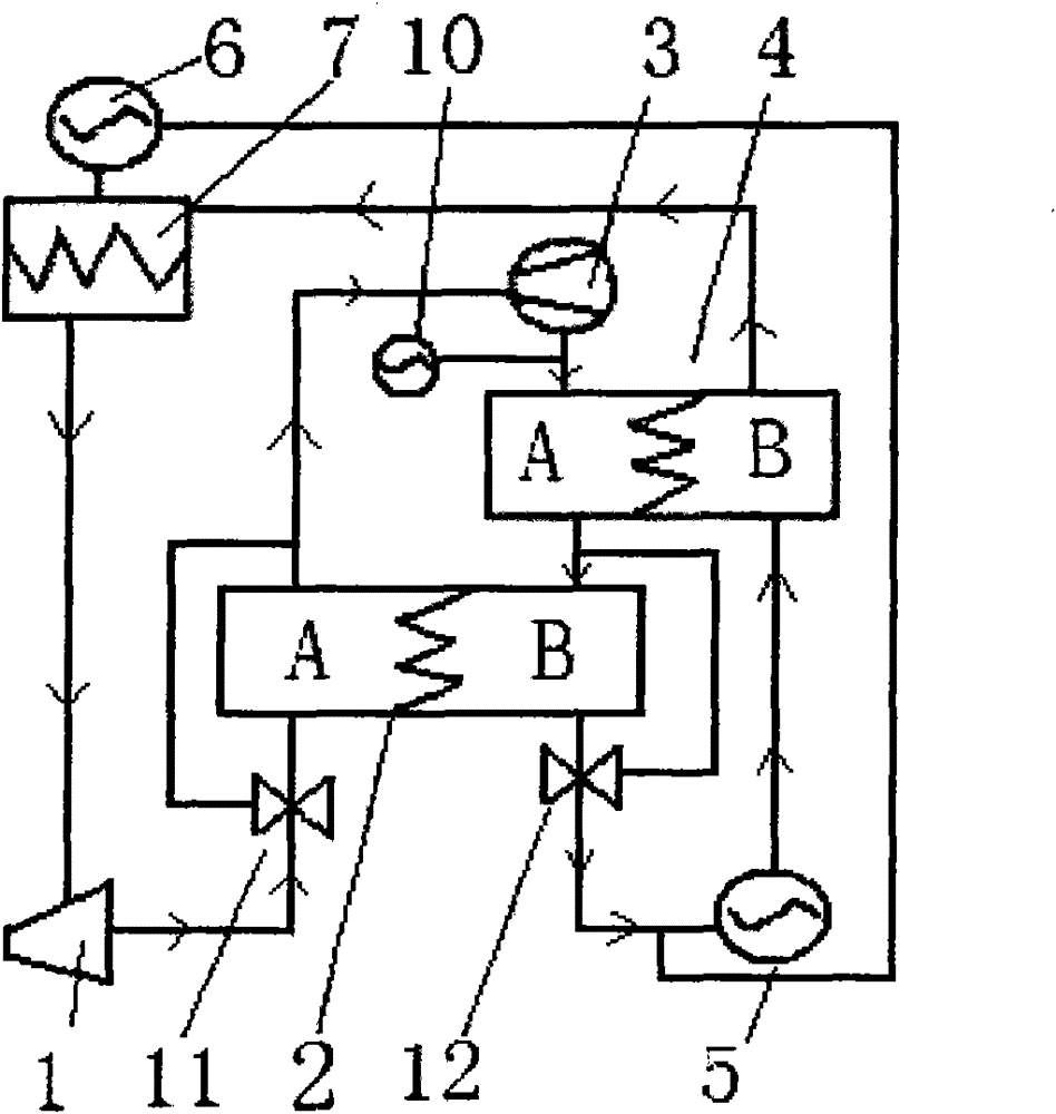
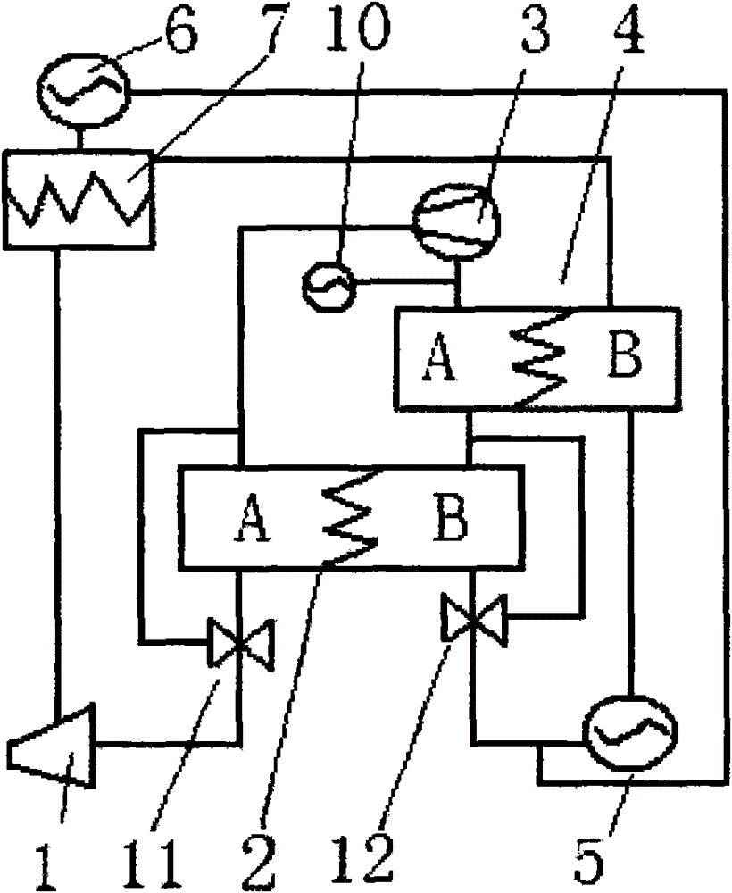
[0068] A device for generating kinetic energy and refrigeration, its structural scheme is: it consists of an expander (1), a heat exchanger (2), a compressor (3), a main heat exchanger (4), a working medium pump (5), Auxiliary working medium pump (6), evaporator (7), vapor-liquid separator (9), non-condensable gas suction pump (10), the working medium outlet of the evaporator (7) is connected with an expander (1) The inlet and the outlet of the expander (1) are connected to the inlet of chamber A of the heat exchanger (2), the outlet of chamber A of the heat exchanger (2) is connected to the inlet of the compressor (3), and the outlet of the compressor (3) is connected to There is the inlet of chamber A of the main heat exchanger (4), and the inlet of the non-condensable gas suction pump (10) is connected to the pipeline between the outlet of the compressor (3) and the inlet of chamber A of the main heat exchanger (4) , the outlet of chamber A of the main heat exchanger (4) is...

Embodiment 3

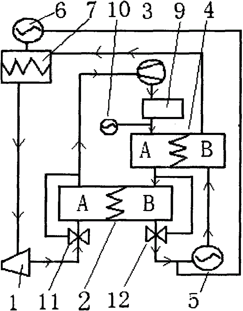
[0070] A method for generating kinetic energy and refrigeration. The difference between this embodiment and Embodiment 1 is that in the initial working cycle of the working cycle described in Embodiment 1, when the vapor state flowing out of the compressor (3) When the temperature of the working medium exceeds the critical temperature of the vapor working medium, let the refrigerator (9) transfer the vapor working medium between the outlet of the compressor (3) and the inlet of the chamber A of the main heat exchanger (4). The temperature is lowered to below the critical temperature of the working medium in vapor state.

[0071] In the work cycle described in this embodiment, the heat exchange efficiency of the main heat exchanger (4) is directly proportional to the efficiency of the work cycle described in this embodiment.

[0072] This embodiment can also be improved to inject an appropriate amount of liquid working medium whose temperature meets the requirements of the work...


PUM


Abstract

The invention relates to a technology and a device that employ a heat source at a normal temperature to generate kinetic energy and refrigerate. The technical content of the work circulation comprises the steps of allowing refrigerant that has absorbed heat and heated up in an evaporator (7) to work in an expander (1), allowing a compressor (3) to carry out compression heating on the vaporous working refrigerant that has worked in the expander (1) and enters the compressor through an A cavity of a heat exchanger (2), allowing the heat exchanger (2) to enable the vaporous working refrigerant that has undergone compression heating in the B cavity to release heat to the vaporous refrigerant that flows from the expander (1) after working and is in the A cavity to produce liquid refrigerant, and allowing the liquid refrigerant that is from the B cavity of the heat exchanger (2) and is in the B cavity of a main heat exchanger to absorb the compression heat of the vaporous refrigerant that has undergone compression heating, is from the compressor (3) and is in the A cavity of the main heat exchanger and then to enter the evaporator (7). The above work circulation simply converts parts of the heat energy to kinetic energy, which does not violate the first law and the second law of thermodynamics and is feasible.

Description

technical field [0001] The present invention relates to the technical field and equipment field of using normal temperature heat source to generate kinetic energy and refrigeration, as well as the technology of separating other substances in the liquid from the liquid by using the energy and cold source generated by the technology of kinetic energy and refrigeration generated by the normal temperature heat source field. The invention also relates to the field of air conditioners manufactured by using the normal temperature heat source to generate kinetic energy and refrigeration technology. Background technique [0002] There are many kinds of energy hidden in nature! Today, the world's main energy source is fossil fuels! The huge demand for energy in the world makes it almost exhausted. At the same time, in the field of refrigeration, it also relies on the method of consuming energy to manufacture cold sources, which exacerbates the energy tension! People are diligently ...

Claims


Application Information

Patent Timeline
Patent Type & Authority Applications(China)
IPC IPC(8): F01K25/10F25B1/00F24F5/00
Inventor 王法文
Owner 王法文
Why Eureka
Try Eureka