Gear interlocking device of five-gear manual transmission

A technology of manual transmission and interlocking device, which is applied in the direction of transmission control, mechanical control device, instrument, etc., can solve problems such as danger, space layout design limitation of multi-speed transmission, transmission damage, etc., and achieve reliable interlocking and easy layout design Effect

Active Publication Date: 2015-05-27
GREAT WALL MOTOR CO LTD
View PDF7 Cites 2 Cited by
  • Summary
  • Abstract
  • Description
  • Claims
  • Application Information

AI Technical Summary

Problems solved by technology

In the above-mentioned transmission, multiple synchronizer mechanisms are often associated with each other. It is desirable to provide interlocking devices for these synchronizer mechanisms to prevent the gears of two or more gears from meshing and transmitting power at the same time, causing damage to the transmission and causing damage to the transmission. failure, which is very dangerous at high speeds
At present, in a multi-speed manual transmission, when entering a certain gear, in order to ensure that the other gears are in neutral, a U-shaped interlocking plate is usually used to lock the shift fork shaft to realize the interlock between the gears. This structure is simple and easy to implement, and is adopted by most products. However, this structure requires that the distance between the shift fork shafts should not be too large, which has great restrictions on the space layout design of the multi-speed transmission, which is not conducive to the layout of the transmission. When the relative distance between the fork shafts is large, the interlock between the gears is difficult to achieve

Method used


Image

  • Gear interlocking device of five-gear manual transmission
  • Gear interlocking device of five-gear manual transmission
  • Gear interlocking device of five-gear manual transmission

Examples


Embodiment Construction

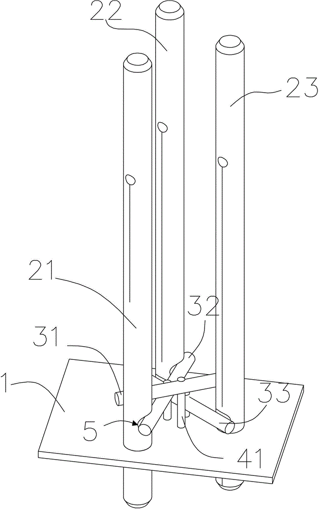
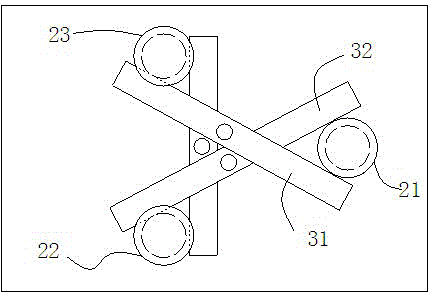
[0017] The present embodiment relates to a five-speed manual transmission gear interlocking device, which is composed of figure 1 , figure 2 As shown, it includes three parallel fork shafts arranged on the transmission case 1, wherein, figure 1 The schematic structure of the transmission case 1 is shown in the figure, which is mainly for showing the connection and positional relationship of other components with it; and based on the three shift fork shafts in the five-speed manual transmission, in this embodiment, the existing transmissions are all used. That is, the three shifting fork shafts are respectively the fifth-reverse gear shifting fork shaft 21, the third and fourth gear shifting fork shafts 22, and the first and second gear shifting fork shafts 23. On the transmission case 1, and can move axially relative to the transmission case 1, three fork shafts are arranged in a triangle in space.

[0018] Three interlocking levers with the same diameter, as well as a firs...


PUM


Abstract

The invention relates to a gear interlocking device of a vehicle transmission and particularly relates to the gear interlocking device of a five-gear manual transmission. The device comprises three shifting fork shafts which are arranged on a transmission body in parallel and can move axially and three interlocking shifting levels which are arranged in a lamination mode along the axial line of the shifting fork shafts and can respectively rotate relative to the transmission body, wherein the three shifting fork shafts are arranged triangularly in space, when the interlocking shifting levels are located at the same side of the central connecting line of two adjacent shifting fork shafts and shifting fork shafts do not move in an axial direction, the interlocking shifting levels are inserted into grooves of the two adjacent shifting fork shafts with allowances; and when one of three shifting fork shafts moves in an axial direction, two interlocking shifting levels which are inserted into the grooves with allowances slide from the grooves and rotate relative to the transmission body, the two interlocking shifting levels are embedded in grooves of anther two shifting fork shafts with allowances, and the allowances are reduced. By the aid of the technical scheme, the reliable interlocking among gears of the transmission is achieved, and the spatial design of the transmission is easy.

Description

technical field [0001] The invention relates to a gear interlocking device for a vehicle transmission, in particular to a gear interlocking device for a five-speed manual transmission. Background technique [0002] Generally speaking, the driving power of a car comes from power devices, such as conventional engines, motors, etc. According to the requirements of vehicle traction, the speed and torque of the engine are converted and transmitted to the wheels through a power transmission device, which is usually called a power transmission device. for the transmission. The working principle of automobile transmission is to change the range of driving force and speed of the automobile by changing the transmission ratio, so as to meet the normal driving of the automobile under various road conditions. With the continuous progress and development of automobile technology, there are more and more types of transmissions. , but are generally divided into two categories: one is the m...

Claims


Application Information

Patent Timeline
Patent Type & Authority Patents(China)
IPC IPC(8): F16H63/34F16H63/32
CPCF16H63/36
Inventor 邱健郭明亮马克刘磊田广召高春洋张喜成
Owner GREAT WALL MOTOR CO LTD
Why Eureka
Try Eureka