
Lower-control water-saving water valve

A technology of water valve and lower section, which is applied in the field of down-controlled water-saving water valves, and can solve problems such as practical application of unseen products, cross-infection, inconvenient hand washing, etc.

Inactive Publication Date: 2013-07-17
成都可益轨道技术有限公司
View PDF5 Cites 0 Cited by
  • Summary
  • Abstract
  • Description
  • Claims
  • Application Information

AI Technical Summary

Problems solved by technology

[0002] For traditional mechanically controlled water valves, the control switches are all set on the top or side of the entire housing. Although the control is convenient, there is a problem when used in public places: the water valve needs to be manually closed after washing hands. There is no guarantee of cleanliness, so there may be cross-infection
Especially in some high-end public places, it is always uncomfortable to touch the switch handle after washing
However, it is difficult to install the traditional water valve switch at the water outlet. Some people also propose to install the existing water valve upside down, so that when the water valve is finally closed, the water flow keeps flowing through the water valve switch handle, but this installation The water flow flows out of the nozzle from bottom to top, the water flow is not easy to control, it is inconvenient to wash hands, and it will cause waste of water, so this method is basically not feasible
[0003] At present, there are no previous patent documents and non-patent literature reports on the water valve whose on-off state is controlled by the switch device at the water outlet below the water valve, and there is no practical application of the above-mentioned products.

Method used


Image

  • Lower-control water-saving water valve

Examples


Embodiment Construction

[0026] Below in conjunction with accompanying drawing, the present invention is described in further detail:

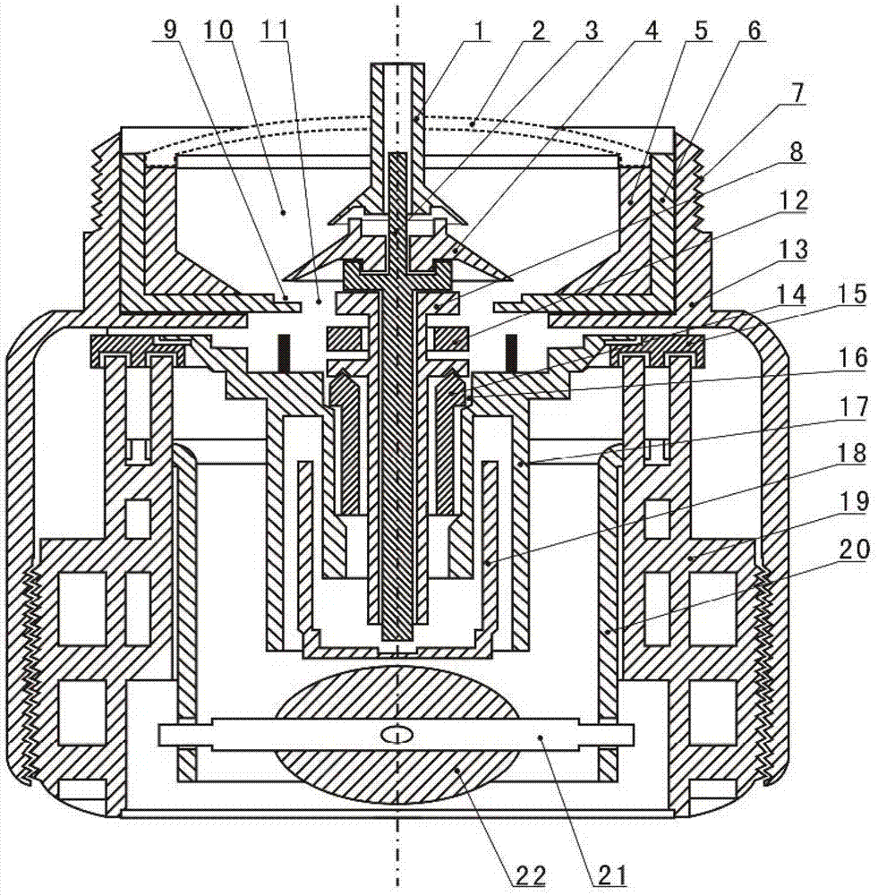
[0027] Such as figure 1 As shown, the present invention includes an outer shell 13, a sealed cavity 6, a central shaft 3, a sealed cover 4, an inner shell 19, a universal ball 22, a set of transmission devices and a limit cylinder 17, wherein: The outer casing 13 includes an upper section and a lower section that communicate with each other. The outer wall of the upper section of the outer casing 13 is provided with an external thread 7 for connecting a water pipe, and the inner wall of the lower section of the outer casing 13 is provided with an internal connection device for connecting the inner casing 19; the sealed cavity 6 is installed on the outer casing 13 In the upper section of the cavity, the central position of the sealing cavity 6 is provided with a water hole 11; the central shaft 3 is located at the central position of the casing 13 and runs through the ...


PUM


Abstract

The invention discloses a lower-control water-saving water valve which comprises an outer casing, a sealing cavity, a center shaft, a sealing cover, an inner casing, a universal ball, a transmission device and a limit barrel. The outer casing comprises an upper section and a lower section which are communicated with each other, a drain hole is arranged at the center of the sealing cavity, the sealing cavity is mounted in a cavity of the upper section of the outer casing, the center shaft penetrates through the upper section and the lower section of the outer casing and can move up and down, the sealing cover is mounted on the center shaft and positioned above the drain hole, the inner casing is mounted in a cavity of the lower section of the outer casing and used for mounting the universal ball, the transmission device and the limit barrel, the universal ball, the transmission device and the limit barrel are mounted in the inner casing, upward power rotatably generated by the universal ball is transmitted to the center shaft through the transmission device, and the limit barrel is used for limiting the transmission device and the center shaft. The opening and closing state of the water valve can be controlled by controlling rotation of the universal ball positioned at a water outlet below the water valve, and the lower-control water-saving water valve has the advantages of accuracy in control, cleanness and sanitation.

Description

technical field [0001] The invention relates to a mechanically controlled water valve, in particular to a down-controlled water-saving water valve which controls the switch state of the water valve through a switch device at the water outlet below the water valve. Background technique [0002] For traditional mechanically controlled water valves, the control switches are all set on the top or side of the entire housing. Although the control is convenient, there is a problem when used in public places: the water valve needs to be manually closed after washing hands. There is no guarantee of cleanliness, so there may be cross-infection. Especially in some high-end public places, it is very uncomfortable to touch the switch handle again after washing. However, it is difficult to install the traditional water valve switch at the water outlet. Some people also propose to install the existing water valve upside down, so that when the water valve is finally closed, the water flow ...

Claims


Application Information

Patent Timeline
Patent Type & Authority Patents(China)
IPC IPC(8): F16K1/00F16K1/32F16K27/02F16K31/44
Inventor 王善举杨吉钊王卓民可乙淋
Owner 成都可益轨道技术有限公司
Learn More