
Multi-waveband parfocal continuous focal length change optical device

An optical device, multi-band technology, applied in optics, optical components, instruments, etc., can solve the problems of difficulty in aberration correction and wide wavelength band, and achieve the effect of compact structure and multi-band aberration correction.

Active Publication Date: 2012-10-10
NO 717 INST CHINA MARINE HEAVY IND GRP
View PDF2 Cites 10 Cited by
  • Summary
  • Abstract
  • Description
  • Claims
  • Application Information

AI Technical Summary

Problems solved by technology

Multi-band, long focal length continuous zoom optical devices are generally suitable for 1 / 3-inch and 1 / 2-inch CCDs, and it is difficult to realize such optical devices that are suitable for 7.6mm×7.6mm and larger image area CCDs, because such optical devices It is the contradictory unity of long focal length and large field of view, coupled with wide band, aberration correction is very difficult

Method used


Image

  • Multi-waveband parfocal continuous focal length change optical device
  • Multi-waveband parfocal continuous focal length change optical device
  • Multi-waveband parfocal continuous focal length change optical device

Examples


Embodiment 1

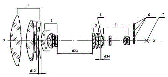
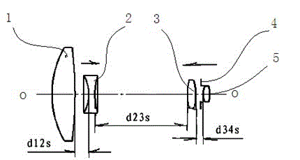
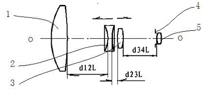
[0044] Example 1: Such as figure 1 Shown is a basic embodiment of the multi-wavelength parfocal continuous zoom optical device of the present invention, which includes 6 mirror groups installed on the same optical axis o-o in the process of continuously changing the focal length; the total length of the optical system remains unchanged; The lens groups are arranged in sequence from front to back: front lens group 1, variable power group 2, compensation group 3, and variable diaphragm group 4, with the front end of the front lens group 1 where light enters as the front end and the end of the image surface 7 as the rear end. , Rear fixed group 5 and filter group 6.

Embodiment 2

[0045] Example 2: It is a further technical solution on the basis of Example 1. The front lens group 1 is used for focusing and is a positive focal power group. From front to back, it is as follows: two low-dispersion double-convex single lenses, one piece of lanthanum flint flat A doublet lens composed of a concave lens and a piece of flint plano-concave lens glued together with a plane glued surface; the zoom group 2 is a negative focal power group, which is as follows from front to back: a piece of heavy flint positive meniscus lens and a piece of heavy crown negative curvature A doublet lens composed of a moon lens, a piece of barium flint positive meniscus lens with a convex surface facing forward, a piece of lanthanum flint negative meniscus lens with a convex surface facing forward, and a piece of heavy barium flint double concave lens with a small concave surface facing forward; the compensation Group 3 is a positive power group, from front to back: two low-dispersion...

Embodiment 3

[0048] Example 3: The difference from Embodiment 2 is that the variable diaphragm group 4 is 0.5 mm away from the front apex of the first lens of the rear fixed group 5 .


PUM


Abstract

The invention relates to a multi-waveband parfocal continuous focal length change optical device, which comprises six lens groups which are arranged on the same optical axis o-o and by which the total length of an optical system is kept constant in a process of continuously changing a focal length, wherein according to the lens groups, one end of a front lens group, which light enters, is used as a front end, and one end of an image surface is used as a rear end; and the six lens groups are the front lens group, a zooming group, a compensation group, a variable diaphragm group, a rear fixed group and a filter lens group from front to back. The multi-waveband parfocal continuous focal length change optical device has the advantages that multiple wavebands are imaged on the same image surface; the problem that an additional lens group is required to be connected or filter lenses with different thicknesses are used for compensating the position of the image surface because the image surface is not parfocal when the image surface is observed at different wavebands is solved; the structure is simplified; and the reliability of a system is improved.

Description

technical field [0001] The invention relates to a multi-band parfocal continuous zoom optical device, which is suitable for a device for realizing multi-band imaging on the same image plane. Background technique [0002] With the wide use of TV sensors in various fields, the optical device as the core component of TV sensors has also been developed rapidly. According to the structure, there are systems such as fixed focus, jump zoom, continuous zoom, jump and continuous zoom, etc. ;According to the range of bands, there are visible light, near-infrared, infrared, ultraviolet and so on. In recent years, for the multi-band (visible light + near-infrared), long focal length and large image size, which can not only monitor large field of view, but also recognize and track in small field of view, have a large operating distance, and can adapt to complex environments such as fog and dust. Continuous zoom optical devices are urgently needed, such as forest fire prevention, road bu...

Claims


Application Information

Patent Timeline
IPC IPC(8): G02B15/173G02B1/00
Inventor 胡际先耿安兵胡锋
Owner NO 717 INST CHINA MARINE HEAVY IND GRP
Learn More