Galvanometer-based multi-point touch system

A multi-touch and touch panel technology, applied in the input/output process of data processing, instruments, electrical digital data processing, etc., can solve the problems of being susceptible to interference, slow response speed of large-size infrared touch screen, etc., and achieve high laser intensity , Solve the effect of weak anti-interference ability and fast response speed

Inactive Publication Date: 2015-02-18
HEFEI UNIV OF TECH
View PDF3 Cites 0 Cited by
  • Summary
  • Abstract
  • Description
  • Claims
  • Application Information

AI Technical Summary

Problems solved by technology

[0003] The purpose of the present invention is to provide a multi-point touch system based on vibrating mirrors to solve the problems of slow response speed and susceptibility to interference in large-size infrared touch screens in the prior art

Method used


Image

  • Galvanometer-based multi-point touch system
  • Galvanometer-based multi-point touch system
  • Galvanometer-based multi-point touch system

Examples


Embodiment Construction

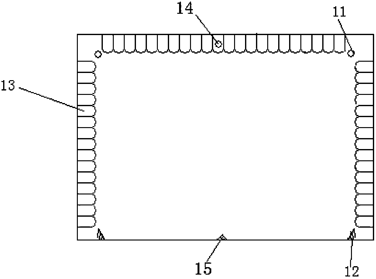
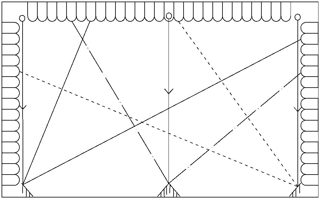
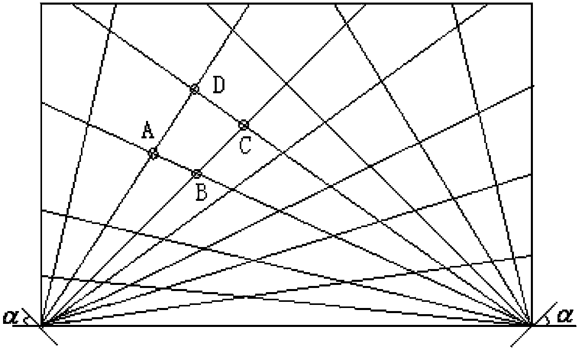
[0016] As shown in Figure 1(a). Install laser emitters 11 at the two upper corners of the touch circuit board, corresponding to the single-sided galvanometers 12 at the same corners on the lower side, that is, the laser emitter at the upper left corner is aligned with the single-sided galvanometer at the lower left corner, and the upper right corner Aim the laser transmitter at the single-sided galvanometer in the lower right corner. The third laser emitter 14 is installed at the upper central position, and the multi-faceted galvanometer 15 is installed at the lower central position as an example for introduction. Wherein the multi-faceted galvanometer 15 selects the galvanometer whose two mirror surfaces form a certain angle for use, as image 3 As shown, the laser emitter 14 is aligned with the vertex of the multi-faceted vibrating mirror 15, and the reflected light from both sides of the polygonal vibrating mirror 15 covers the entire infrared touch screen. The upper side...


PUM


Abstract

The invention discloses a galvanometer-based multi-point touch system. The galvanometer-based multi-point touch system comprises a touch panel, wherein laser emitters are arranged at two adjacent corner positions of the touch panel; single-sided galvanometers are arranged at the other two adjacent corner positions of the touch panel; emergent light of each laser emitter irradiates to a reflecting surface of a single-sided galvanometer on the same edge of the touch panel with the each laser emitter; a third laser emitter is arranged between the two laser emitters; a multi-sided galvanometer is arranged between the two single-sided galvanometers; emergent light of the third laser emitter irradiates to the multi-sided galvanometer; and besides the outer edge of the touch panel where the two single-sided galvanometers and the multi-sided galvanometer are arranged, a plurality of light-sensitive receiving tubes are distributed on the other three edges of the touch panel respectively. The galvanometer-based multi-point touch system has the characteristic of high response speed, is applicable to occasions where relatively strong interference is caused to the wavelength of the conventional infrared touch screen and effectively overcomes the defect that the infrared touch screen has week interference resistance.

Description

technical field [0001] The invention relates to the field of touch screens, in particular to a vibrating mirror-based multi-point touch system. Background technique [0002] With the development of science and technology, touch screens are also developing from traditional single-point touch to multi-touch. Most of the multi-point touch screens that appear at present are capacitive touch screens and computer vision-based. This type of touch screen has high cost and low anti-interference. weak, long life and other shortcomings. The infrared touch screen not only overcomes the above shortcomings, but also has the advantages of convenient installation, long service life, and high light transmission, especially in large-scale applications. Most of the existing large-size infrared touch screens are based on infrared tubes, and the location of the touch is judged according to the blocking of the optical path. In order to avoid the appearance of "ghost points", some have added z d...

Claims


Application Information

Patent Timeline
Patent Type & Authority Patents(China)
IPC IPC(8): G06F3/042
Inventor 吕国强胡跃辉李小哲吴娟尹静施承佩
Owner HEFEI UNIV OF TECH
Why Eureka
Try Eureka