Anti-theft door and window automatic detection method based on network
An automatic detection, door and window technology, applied in the direction of anti-theft alarm mechanical activation, open alarm, etc., can solve the problem of inability to accurately and remotely notify users, unable to know the real-time status of target doors and windows, etc., to achieve convenient historical records and convenient query. Effect
- Summary
- Abstract
- Description
- Claims
- Application Information
AI Technical Summary
Problems solved by technology
Method used
Image

Examples
Embodiment Construction
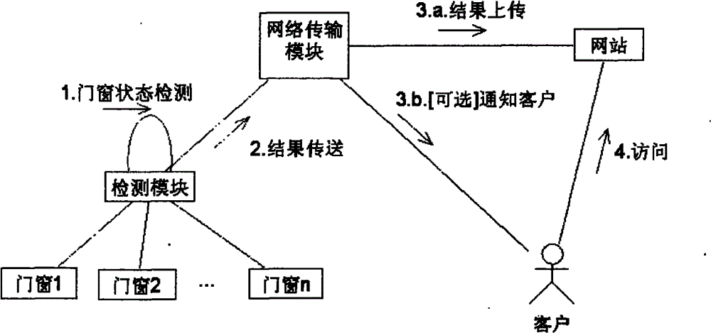
[0012] Concrete working steps of the present invention are as figure 1 shown. The automatic detection module detects the closed state of the target door and window. Once the target state changes, the automatic detection module generates a meaningful message, which can be stored in the memory of the detection module and sent to the network connected to the Internet for transmission. Module, upload to the specified website. When the user needs to view the state change record of the target door and window, he can log in to the website to view it.
[0013] In a specific embodiment, when the state of the target door and window changes, the network transmission module can take technical means to directly notify the client of the message while uploading the message to the website. This technical means is declared in Chinese patent ZL201120417607.1.
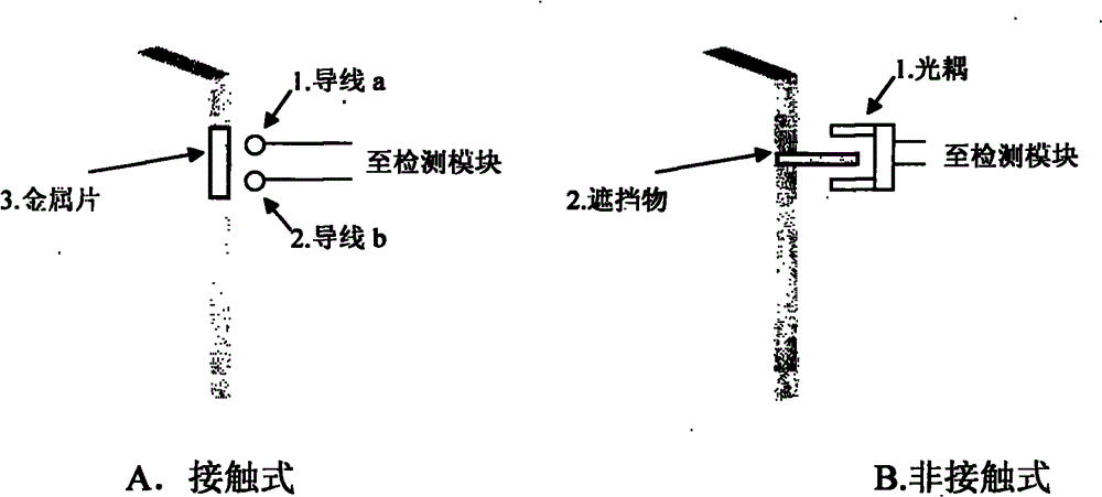
[0014] The automatic detection module can be connected with the target door and window in a contact or non-contact manner.
[0015]...
PUM
 Abstract
Description
Claims
Application Information
 - R&D
- Intellectual Property
- Life Sciences
- Materials
- Tech Scout
- Unparalleled Data Quality
- Higher Quality Content
- 60% Fewer Hallucinations
Browse by: Latest US Patents, China's latest patents, Technical Efficacy Thesaurus, Application Domain, Technology Topic, Popular Technical Reports.
© 2025 PatSnap. All rights reserved.Legal|Privacy policy|Modern Slavery Act Transparency Statement|Sitemap|About US| Contact US: help@patsnap.com