Electrical precipitator

A technology of electrostatic precipitator and electric field electrode, which is applied in the field of dust removal, can solve the problems of exacerbating dust emission exceeding the standard, dust is not easy to charge, adsorption, and emission exceeding the standard, so as to reduce economic losses and shorten process downtime

Active Publication Date: 2012-10-17
FUJIAN LONGKING
View PDF8 Cites 3 Cited by
  • Summary
  • Abstract
  • Description
  • Claims
  • Application Information

AI Technical Summary

Problems solved by technology

Due to the short residence time of the fine dust in the rear electric field of the traditional electrostatic precipitator, it is difficult for the dust to be fully charged and adsorbed, or it is too late to deposit on the wall and is taken out of the

Method used


Image

  • Electrical precipitator

Examples


Example Embodiment

[0020] The core of the present invention is to provide an electric precipitator, which prolongs the time of dust in the rear electric field to reduce dust emission.

[0021] In order to enable those skilled in the art to better understand the technical solutions of the present invention, the present invention will be further described in detail below with reference to the accompanying drawings and specific embodiments.

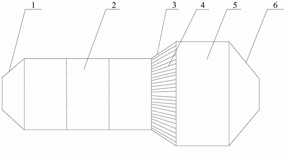
[0022] Please refer to figure 1 The embodiment of the present invention discloses an electric precipitator, which includes a dust removal main body and an inlet horn 1 and an outlet horn 6 arranged at both ends of the dust removal main body. The dust removal main body includes a plurality of sections close to the outlet horn 6 and has a larger cross-sectional area than the end close to the inlet horn 1. The cross-sectional area of ​​the end of the dust removal split.

[0023] At work, after the flue gas enters the electrostatic precipitator through the inlet horn 1,...


PUM


Abstract

The invention discloses an electrical precipitator, comprising a dedusting main body with an electric field polar plate arranged inside the dedusting main body, and an inlet loudspeaker and an outlet loudspeaker which are arranged on two ends of the dedusting main body, wherein the dedusting main body comprises a plurality of dedusting sections in which cross sectional area nearby the outlet loudspeaker end is larger than that nearby the inlet loudspeaker. After smoke enters the electrical precipitator through the inlet speaklouder, large dust particle with strong charge is collected by the front dedusting sections with small cross sectional area under actions of natural sedimentation and electric field force; the residual fine dust is collected by the back dedusting sections with large cross sectional area. As the back dedusting sections have large cross sectional area, the flow velocity of the dusty gas declines so as to increase residence time, charged time and time of motion under the electric field force of the fine dust in the dedusting sections, so that the dust is easy to charge or deposit on the polar plate; therefore, the dedusting efficiency is improved, the dust emission is reduced and the excessive emission is avoided.

Description

technical field [0001] The invention relates to the technical field of dust removal, in particular to an electric dust collector. Background technique [0002] Electrostatic precipitators can be divided into circular electrostatic precipitators (used in gas dust removal fields such as blast furnaces and converters) and square electrostatic precipitators (that is, traditional electrostatic precipitators that are widely known) according to the different cross-sectional shapes. Traditional electrostatic precipitators can be designed with different electric fields, and the length of each electric field can be the same or different, but the cross-sectional shape of each electric field is the same. After the flue gas enters the electrostatic precipitator from the inlet horn, it passes through each electric field at the same flow rate, and then is discharged through the outlet horn. [0003] Because the dust particle size and dust concentration in the flue gas are distributed diff...

Claims


Application Information

Patent Timeline
IPC IPC(8): B03C3/34
Inventor 寇向上黄星赖栋文宋金宋俊
Owner FUJIAN LONGKING
Why Eureka
Try Eureka