Machine tool

A technology of machine tools and moving mechanisms, applied in machine tool parts, metal processing machinery parts, clamping and other directions, can solve the problem of not being able to shorten the tool change time, and achieve the effect of shortening the tool change time and improving the tool change efficiency.

Active Publication Date: 2012-10-17
BROTHER KOGYO KK
View PDF5 Cites 9 Cited by
  • Summary
  • Abstract
  • Description
  • Claims
  • Application Information

AI Technical Summary

Problems solved by technology

Therefore, the tool change time cannot be shortened

Method used


Image

  • Machine tool
  • Machine tool
  • Machine tool

Examples


Embodiment Construction

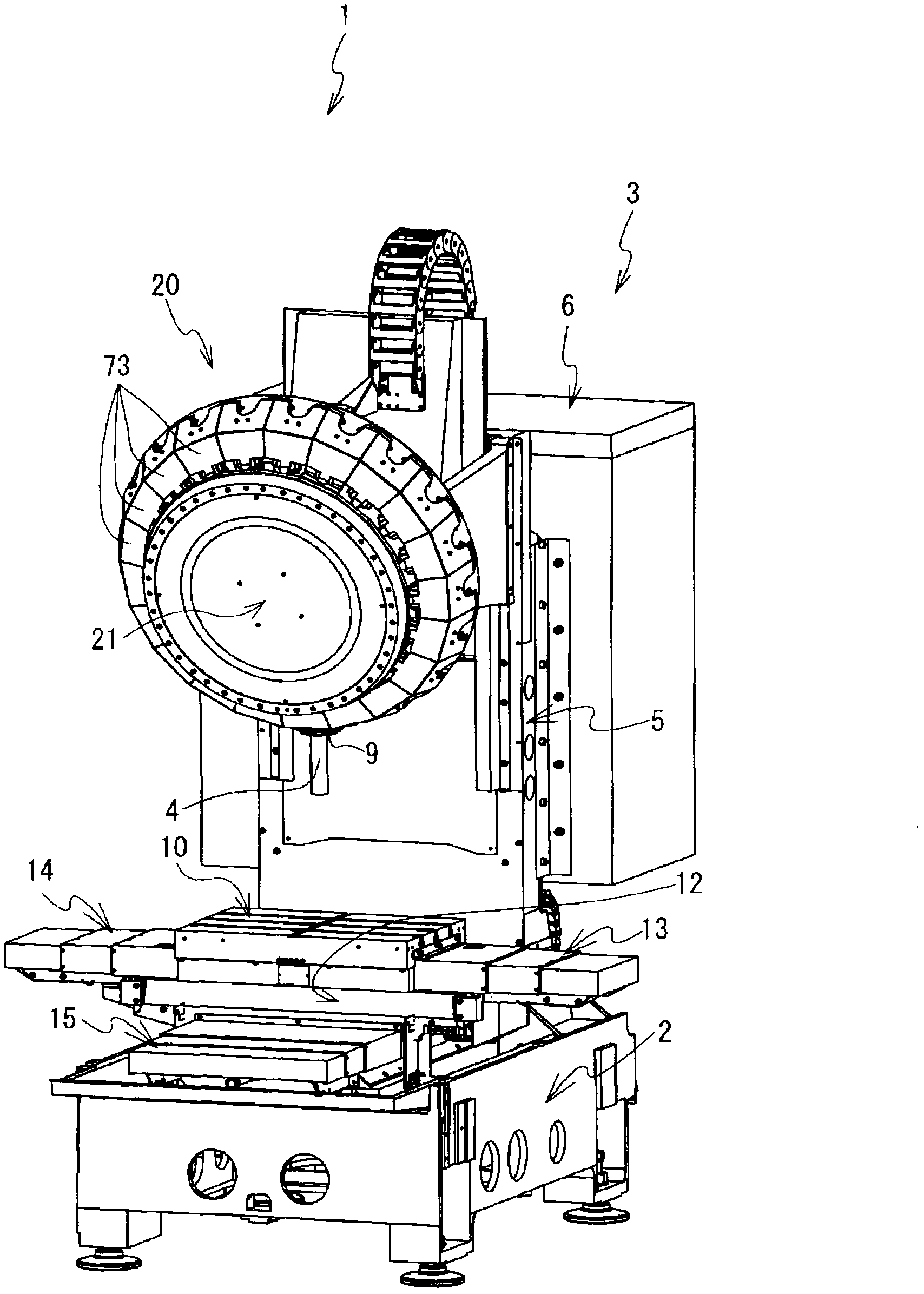
[0018] Hereinafter, a machine tool 1 according to a first embodiment of the present invention will be described based on the drawings. figure 1 The front direction, the depth direction, the right side, and the left side of the paper refer to the front, the rear, the right side, and the left side of the machine tool 1, respectively. The left-right direction of the machine tool 1 is the X-axis direction, the front-back direction is the Y-axis direction, and the up-down direction is the Z-axis direction. The machine tool 1 has a base 2, a machine tool body 3, a tool changer 20, and a protective cover (not shown). Base 2 is made of iron. The machine tool body 3 is located on the upper part of the base 2 and cuts the workpiece. The tool changer 20 is located on the upper part of the machine tool body 3 , and replaces the tool 4 mounted on the spindle 9 of the machine tool body 3 . The protective cover surrounds the machine tool main body 3 and the tool changer 20 .

[0019] The...


PUM


Abstract

The present invention provides a machine tool capable of shortening tool changing time and increasing machining production rate. When the machine tool begins to change a tool, a main shaft directionally motions; a main shaft head rises from a machining position to a Z-axis original point with a Z-axis highest speed (S11); when the main shaft finishes the directional motion (S12: YES), the main shaft head rises from the Z-axis original point to an ATC original point with a Z-axis ATC rising speed (S13); when the main shaft head arrives the ATC original point (Z615) (S13), a tool changer performs driving; the tool changer rotates to position the next tool (S14); then the main shaft head decreases from the ATC original point to the Z-axis original point (S15) with a speed same as the A-axis highest speed; and then, the main shaft head decreases from the Z-axis original point to the machining starting position of a workpiece to be machined with a Z-axis highest speed (S16). The machine tool uses a tool to perform machining on the workpiece to be machined.

Description

technical field [0001] The invention relates to a machine tool. Specifically, it relates to a machine tool that moves a spindle head in an ATC area to replace a tool mounted on the spindle. Background technique [0002] The machine tool performs the spindle orientation action in advance when performing automatic tool change. The machine tool needs to stop the spindle at a rotational angle position where a tool change can be performed. Spindle orientation operation is the operation of positioning the spindle at the rotational angle position where tool change can be performed. When the machine tool is changed, the movement of the spindle head rising to the origin of the Z axis and the movement of the spindle orientation are carried out at the same time. The Z-axis origin is the mechanical origin of the Z-axis. The machine tool starts to decelerate the movement of the spindle head to the Z-axis origin after the spindle orientation movement is completed. After that, the mac...

Claims


Application Information

Patent Timeline
Patent Type & Authority Applications(China)
IPC IPC(8): B23Q3/155
CPCB23Q3/15506B23Q15/22B23Q2220/002B23Q2716/00
Inventor 伊藤惠史阿久泽智规
Owner BROTHER KOGYO KK
Why Eureka
Try Eureka