Replaceable removal tool structure

A technology for dismantling tools and tool bodies, applied in hand-held tools, manufacturing tools, etc., can solve the problems of reducing work efficiency, increasing working hours, and increasing costs

Inactive Publication Date: 2012-10-17
杨仁永
View PDF9 Cites 4 Cited by
  • Summary
  • Abstract
  • Description
  • Claims
  • Application Information

AI Technical Summary

Problems solved by technology

[0007] Generally, the tie rod adapters of automobiles have different specifications and sizes, so that the removal tools need to be purchased separately according to different specifications and sizes. For the industry, there will be a problem of cost increase. As for the use, it is also necessary to find the desired one. For the user, disassembly tools of different sizes will undoubtedly increase the man-hours and reduce work efficiency.

Method used


Image

  • Replaceable removal tool structure
  • Replaceable removal tool structure
  • Replaceable removal tool structure

Examples


Embodiment Construction

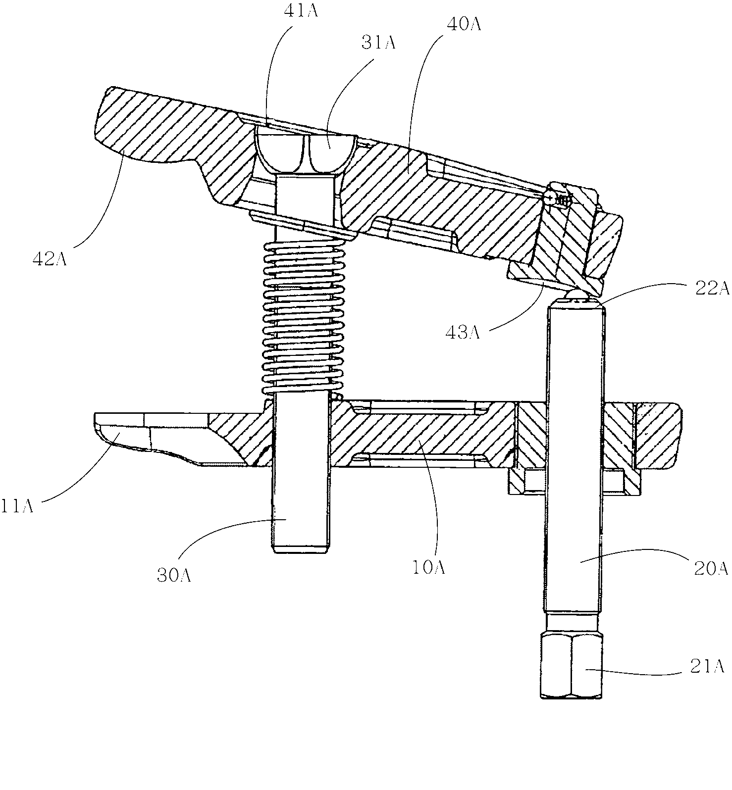
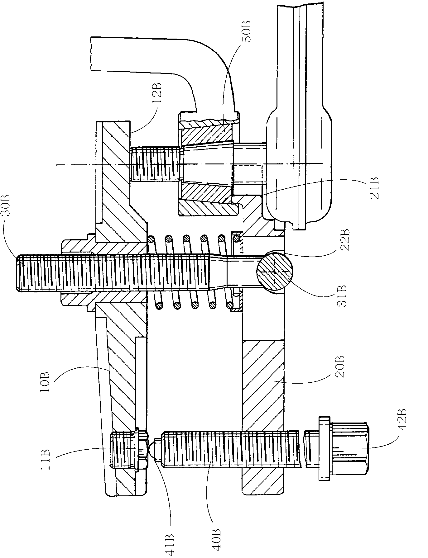
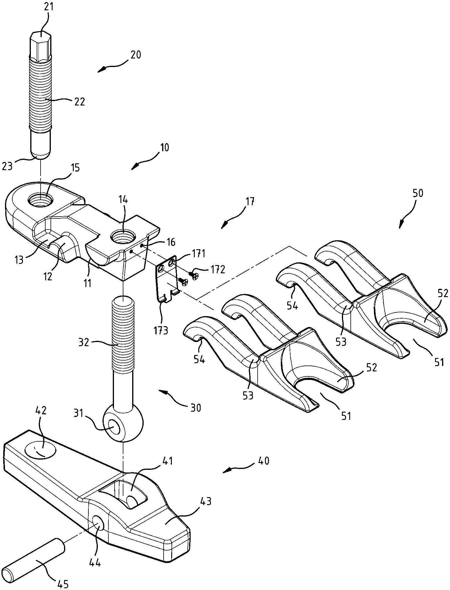
[0027] see Figure 3 ~ Figure 6 Shown is a preferred embodiment of the structure of the replaceable removal tool of the present invention, but these embodiments are for illustration purposes only, and are not limited by this structure in the patent application.

[0028] The replaceable demounting tool structure of the present invention comprises:

[0029] A tool body 10, which is assembled with an adjusting screw 20 as a lead screw at one end, wherein one end of the adjusting screw 20 is provided with a driving end 21, the other end is provided with a top end 23, and the other end of the tool body 10 is fixed with a longitudinal strut 30, wherein the predetermined position of the tool body 10 is provided with a fixed hole 14 in the form of an internal thread, and the support rod 30 is provided with a fixed portion 32 in the form of an external thread corresponding to the fixed hole 14, so that the support rod 30 can be The relative screw lock is fixed on the tool body 10, the...


PUM


Abstract

The invention provides a replaceable removal tool structure, mainly comprising a tool body, a rocker member, and an actively replaceable detent member. One side of the detent member is provided with an upper guide arc edge and a lower guide arc edge which can hang on an upper guide arc portion and a lower guide arc portion of the tool body. And the other side of the detent member which faces an abutting area of the rocker member is provided with a groove-shaped detent portion, and a detent edge is arranged in the detent portion. The detent member of the invention, which is creative in design, can actively combine the tool body on the basis of different specification changes of the detent portion, and can match forms with multiple sizes and specifications so as to enhance the practical use.

Description

technical field [0001] The invention relates to a replaceable dismantling tool structure, especially a tool structure for dismantling the steering rod joint of an automobile, which is a new invention design. Background technique [0002] Press, when the tie rod adapter of the general automobile steering machine is repaired and replaced, it is necessary to replace the adapter and the pivot joint of the connecting rod before replacing it. Generally, in the disassembly method of the traditional adapter, first loosen the locked nut Finally, perform the disassembly action of knocking and separating the adapter and the connecting rod pivot group. However, because the adapter and the connecting rod pivot have a considerable degree of tightness, it is not easy to knock the connecting rod pivot joint. Hitting action, but must first use an auxiliary tool to insert between the adapter and the connecting rod and knock to separate the two for a certain distance, and then use a hammer to ...

Claims


Application Information

Patent Timeline
Patent Type & Authority Applications(China)
IPC IPC(8): B25B27/02
Inventor 杨仁永
Owner 杨仁永
Why Eureka
Try Eureka