Discharging method for electroplated electronic components

A technology for electronic components and driving motors, which is applied in the field of discharging of electronic components after electroplating, can solve the problems of easily damaged drums, high labor intensity, time-consuming and other problems, and achieves the effects of high efficiency, convenient operation and time saving.

Inactive Publication Date: 2012-10-17
SHANGHAI DINGHONG ELECTRONICS
View PDF7 Cites 5 Cited by
  • Summary
  • Abstract
  • Description
  • Claims
  • Application Information

AI Technical Summary

Problems solved by technology

Such an operation method is time-consuming, inefficient, and has the disadvantages of high labor intensity and easy damage to the drum.

Method used


Image

  • Discharging method for electroplated electronic components
  • Discharging method for electroplated electronic components
  • Discharging method for electroplated electronic components

Examples


Embodiment 1

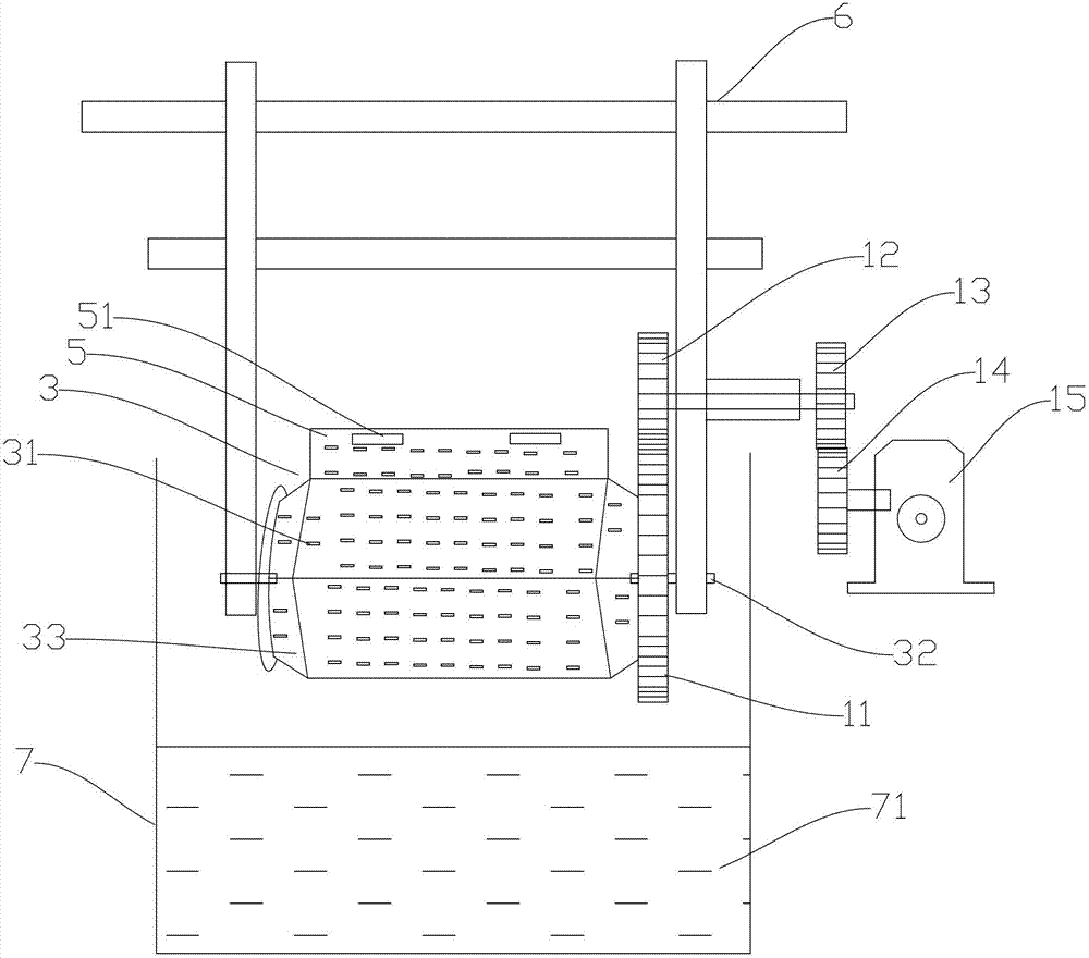
[0022] like figure 1 As shown, the drum device used in the present invention includes a drum 3 , and the drum 3 includes a drum body 33 . An opening (not shown in the figure) is provided on the body of the drum 33 . The drum body 33 is hinged with a top cover 34 that can close the opening. A through hole 31 is provided on the cylinder wall of the drum body 33 . The drum 3 is rotatably arranged on the bracket 6 through the shaft 32 . The drum 3 is provided with a top cover 5, the top cover 5 is provided with a knob 4, and the drum body is provided with a groove matching the knob 4 (not shown in the figure).

[0023] A knob 51 is provided on the top cover 5 . The drum body 33 is provided with a card slot (not shown) matching the knob 51 . The knob 51 cooperates with the slot to connect the top cover 5 with the drum body 33 . The way of cooperation between the knob 51 and the slot can be realized by using the existing technology, which will not be repeated here.

[0024] T...

Embodiment 2

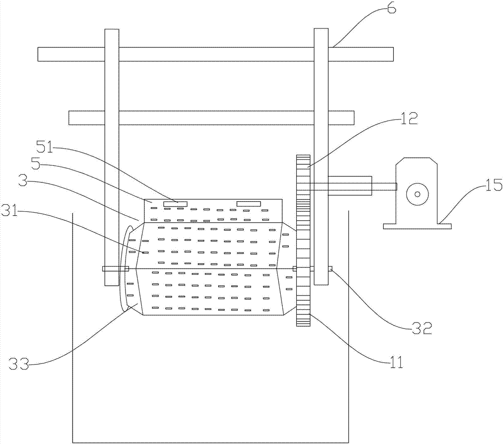
[0027] like figure 2 As shown, the difference between this embodiment and Embodiment 1 is that the second gear 12 and the third gear 13 in Embodiment 1 are not provided in this embodiment. The first gear 11 meshes with the fourth gear 14 .

Embodiment 3

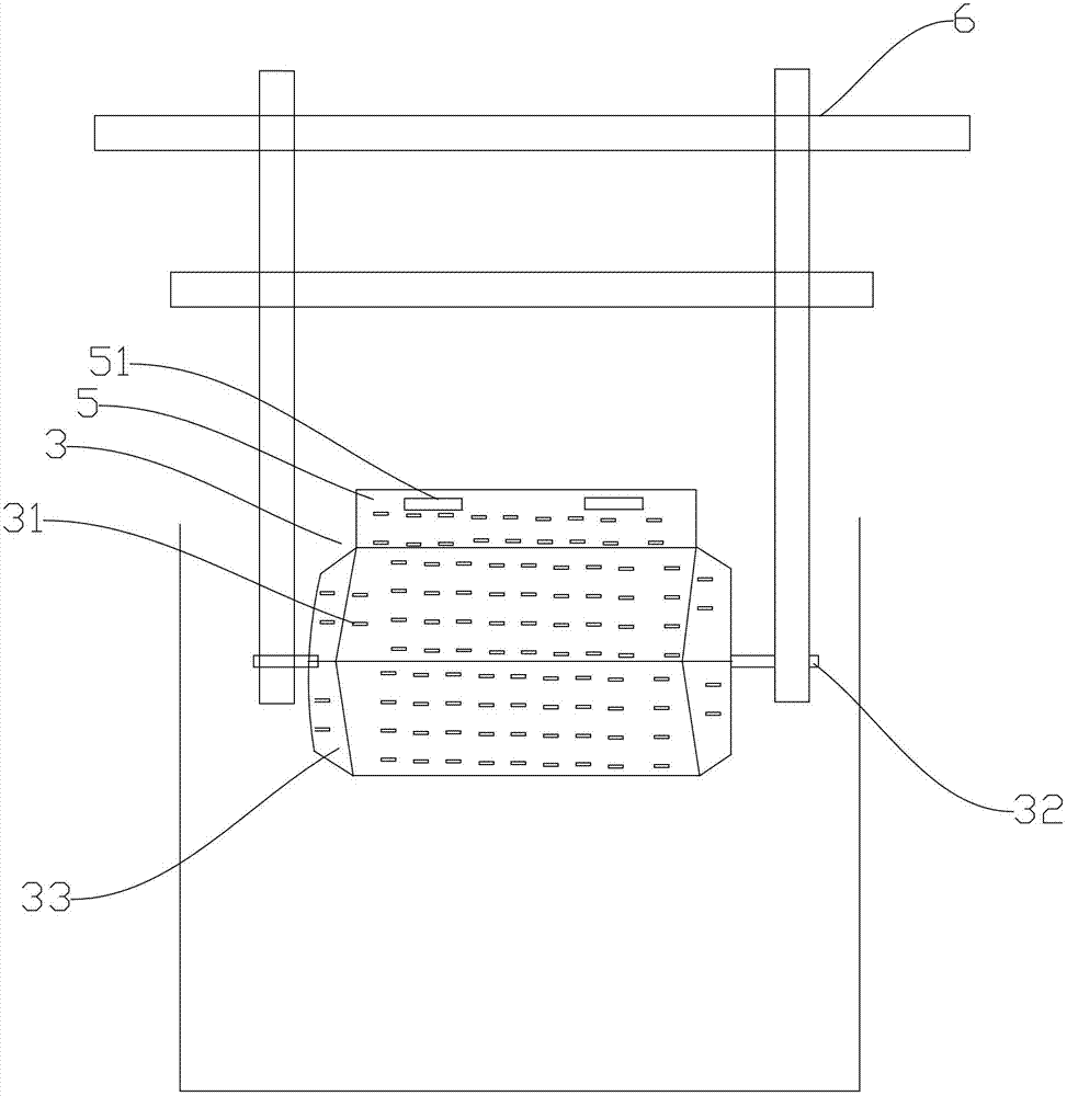
[0029] like image 3 As shown, the difference from Embodiment 1 is that the driving motor 15 and the transmission device are not provided in this embodiment. In this embodiment, the drum 3 is manually rotated by the operator.


PUM


Abstract

The invention discloses a discharging method for electroplated electronic components. The discharging method is characterized in that a barrel provided with through holes is put into water, and is rotated or rocked to separate electronic components from an inner wall of the barrel by action of water, and the electronic components are discharged from an opening of the barrel. The discharging method for the electroplated electronic components provided by the invention is operated conveniently, is capable of conveniently taking out electronic components from the barrel and saving time, and is featured with high efficiency. In a device used by the method, structures are simple, and a top cover is connected with a barrel main body through a knob, so that electronic components are taken out conveniently from the barrel. By transmission of gears, manual operations are realized, and automation production also can be realized by action of a motor.

Description

technical field [0001] The invention relates to a material discharging method after electroplating of electronic components. Background technique [0002] Electroplating is divided into rack plating, barrel plating, continuous plating and brush plating, which are mainly related to the size and batch size of the parts to be plated. Rack plating is suitable for general-sized products, such as car bumpers, bicycle handlebars, etc. Barrel plating is suitable for small parts such as fasteners, washers, pins, etc. Continuous plating is suitable for mass-produced wire and strip. Brush plating is suitable for partial plating or restoration. The electroplating solution includes acidic, alkaline, acidic and neutral solutions with chromium admixture. No matter what kind of plating method is used, the plating tanks and hanging tools that are in contact with the products to be plated and the plating solution should have a certain degree of safety. Versatility, and in the actual produ...

Claims


Application Information

Patent Timeline
Patent Type & Authority Applications(China)
IPC IPC(8): C25D17/20C25D21/00
Inventor 付廷军刘同华蒋利平
Owner SHANGHAI DINGHONG ELECTRONICS
Why Eureka
Try Eureka