Flange mounting structure at bottom of inner barrel of washing machine and washing machine
An installation structure, washing machine technology, applied in the washing machine field, to achieve the effect of low installation cost and simple structure
- Summary
- Abstract
- Description
- Claims
- Application Information
AI Technical Summary
Problems solved by technology
Method used
Image
Examples
Embodiment 1
[0032] Such as Figure 4 As shown, in this embodiment, the flange main body 40 is provided with up and down permeable holes 5 in the area between two adjacent mounting feet 41, so that the washing machine can circulate between the inner and outer tubs of the working wash water. At the same time, the cleaning particles are prevented from entering the inner barrel through the flange 4. The flange of this embodiment is an improved design on the basis of the existing flange. The main body of the ordinary flange is extended radially outward to between two adjacent mounting feet 41 to form the flange main body of the present invention. The thickness of the extension part can be less than the thickness of the flange body, and the extension part is provided with a water-permeable hole 5 whose size is smaller than the size of the cleaning particles.
Embodiment 2
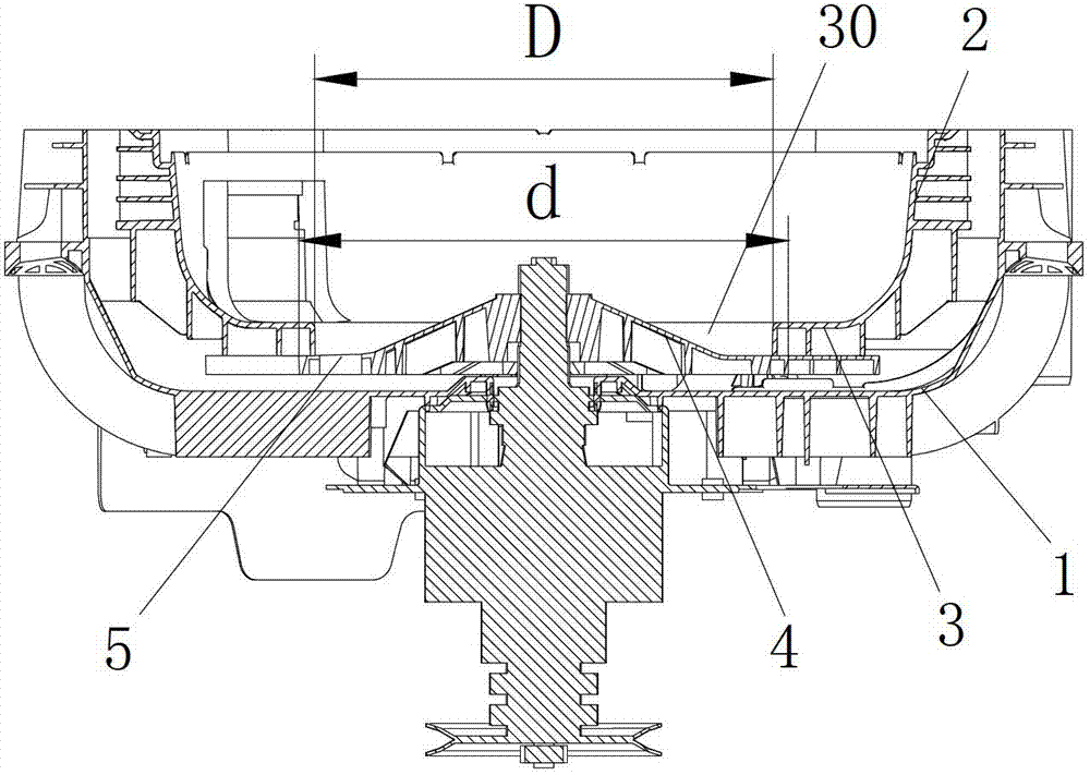
[0034] Such as Figure 5 As shown, the bottom 3 of the inner tub is provided with water permeable holes 5 that communicate up and down along the area around the opening 30. This embodiment is an improved design of the existing bottom structure of the inner tub, reducing the diameter of the opening 30 at the bottom of the inner tub, and adding a water-permeable hole 5 in the circumferential ring area.
Embodiment 3
[0036] The permeable hole 5 of the present invention is a straight long slit structure or a curved long slit structure. The long slit structure will not reduce the strength of the flange or the bottom of the inner bucket. Because most of the thread waste in the washing water is collected by the thread waste filtering structure, a small part of the thread waste is small and dispersed into thin strips. Therefore, the water permeable The hole will not cause clogging of thread chips.
[0037] A preferred solution is that the water permeable hole has a funnel structure with a reduced size from top to bottom. This structure increases the flow rate of the drain when passing through the permeable hole, which is conducive to impacting the thread chips passing through, and further reduces the possibility of blockage.
[0038] Since the center of the flange body rises, the drainage water flows in the radial direction to the edge, so the permeable holes are designed as a long slit structure d...
PUM
 Abstract
Description
Claims
Application Information
 - R&D
- Intellectual Property
- Life Sciences
- Materials
- Tech Scout
- Unparalleled Data Quality
- Higher Quality Content
- 60% Fewer Hallucinations
Browse by: Latest US Patents, China's latest patents, Technical Efficacy Thesaurus, Application Domain, Technology Topic, Popular Technical Reports.
© 2025 PatSnap. All rights reserved.Legal|Privacy policy|Modern Slavery Act Transparency Statement|Sitemap|About US| Contact US: help@patsnap.com


