Feeder channel for diluting fluid

A feeder and fluid technology, applied in the direction of textiles and papermaking, paper machine, paper machine wet end, etc., can solve the problem that the channel that cannot be accurately and reliably adjusted by the diluted fluid, cannot be adjusted accurately, and the channel cannot be blocked, etc. question

Inactive Publication Date: 2012-10-17
VAAHTO PAPER TECH
View PDF1 Cites 2 Cited by
  • Summary
  • Abstract
  • Description
  • Claims
  • Application Information

AI Technical Summary

Problems solved by technology

A problem with the solutions according to the prior art is that with these solutions a precisely and reliably regulated passage of the dilution fluid into the slurry flow space is not obtained, since the throttling devices in these solutions are generally conical and the dilution water Impurities can be trapped between the conical restriction and the proportional orifice
Especially if retention, i.e. a fluid capable of holding particles is used as dilution water, this may result in gaps at the edges of the restriction and proportional orifice, where the dilution fluid enters the path of the slurry flow cannot be blocked or precisely regulated
[0004] Another disadvantage of the prior art is the susceptibility to vibrations of the base of the proportional device (or in other words the throttling / regulating device) and its arm (the base is at the end of the arm) of the proportional device (or in other words the throttling / regulating device) for diluting the fluid presented in the aforementioned publication

Method used


Image

  • Feeder channel for diluting fluid
  • Feeder channel for diluting fluid
  • Feeder channel for diluting fluid

Examples


Embodiment Construction

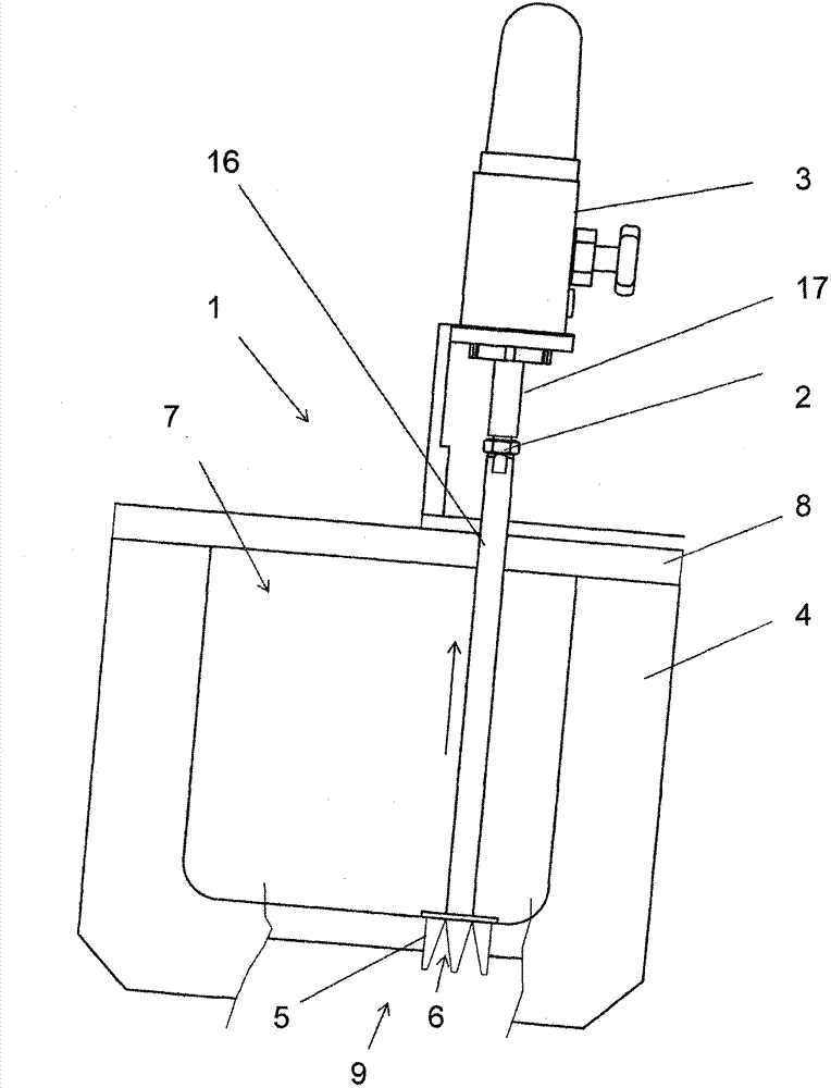
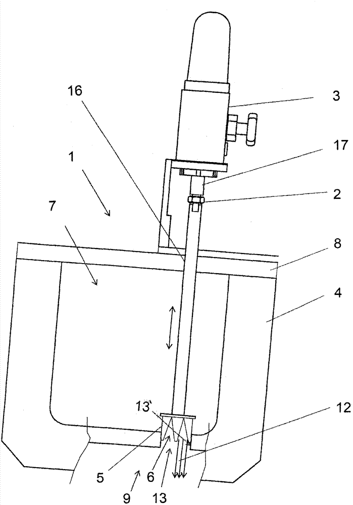
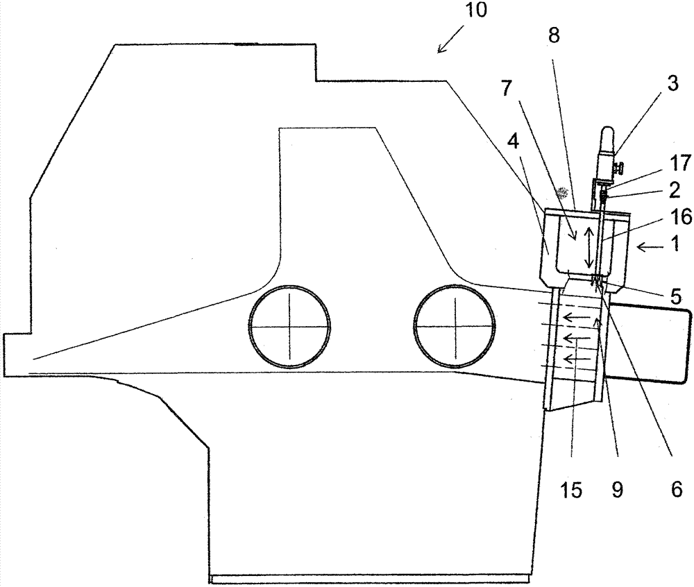
[0020] The feeder channel 1 according to the invention for a dilution fluid, for example for dilution water, consists of Figure 1a and Figure 1b Presentation, the feeder channel is connected with the head box 10 of the paper machine (the head box 10 is presented in Figure 1c and Figure 1d Middle), the feeder channel 1 comprises one or more reservoir-type spaces 7, eg chambers for receiving a dilution fluid such as water, and one or more walls 4, 8 form the spaces 7. A hole 13 is formed in the reservoir type space 7, through which hole dilution fluid can be led into the slurry flow space 9 of the headbox. The flow space 9 comprises a plurality of individual flow channels, such as pipes, i.e. the flow space 9 is usually not an open flow space, but flow space types comprising only one flow channel are also conceivable (the flow space 9 is not shown in the figure for more details).

[0021] One or more cut-off / regulating devices 5 are fitted in said feeder channel 1, presen...


PUM


Abstract

Feeder channel (1) for diluting fluid, such as for diluting water, which feeder channel is in connection with the headbox (10) of a paper machine and comprises one or more reservoir-type spaces (7), such as a chamber, for receiving diluting fluid, which space comprises one or more walls (4), and that an aperture (13) is formed in the reservoir-type space (7), via which aperture the diluting fluid can be conducted into the stock flow space (9) of the headbox, and that one or more shut-off / adjustment means (5), with which the flow of diluting fluid via the aforementioned aperture (13) can be adjusted, is fitted into the feeder channel (1), and that the shutoff / adjustment means (5) is a shut-off / adjustment means that can be moved in the longitudinal direction of an aperture that is in connection with the aperture (13) formed in the wall (4) of the reservoir-type space, and that in the shutoff / adjustment means (5) that is partly or wholly inside the aperture there are one or more cavities and / or recesses (6, 14), via which the flow of diluting fluid from the reservoir-type space (7) either directly or via an intermediate piece (11) into the stock flow space (9) can be adjusted by moving the shut-off / adjustment means (5) in the aperture (13), and that the shut-off / adjustment means (5) comprises a support surface or support surfaces (6''), which can rest on the inside surface (13') of the aperture (13) for preventing vibration of the adjustment means (5) caused by the flow of the diluting fluid at least during operation of the shut-off / adjustment means.

Description

technical field [0001] The invention relates to a feeder channel for a dilution fluid, such as for dilution water, as defined in the preamble of claim 1, which feeder channel is mounted in connection with a headbox of a paper machine for feeding dilution water to in the slurry flow. Background technique [0002] Solutions are known in the field for a feeder channel for dilution fluid, for example for dilution water, which feeder channel is connected to the headbox of the paper machine, with the purpose of supplying dilution water to the stock flow. One such solution is described in publication FI112260B, which provides a proportional device for a headbox of a paper machine, in particular for feeding fluid into the stock flow of the paper machine (to the input point of the stock) middle. The solution presented in this publication consists of at least one chamber, which functions as a receiving space for the flowing medium, and connected to this chamber is a proportional ori...

Claims


Application Information

Patent Timeline
Patent Type & Authority Applications(China)
IPC IPC(8): D21F1/06
CPCD21F1/022D21F1/02D21F1/024D21F1/08
Inventor E·尼米嫩H·克隆霍尔姆
Owner VAAHTO PAPER TECH
Why Eureka
Try Eureka