Method and vehicle for determining characteristics of a valve installed in a vehicle

A vehicle and characteristic technology, applied in the direction of cooling device control device, measuring device, engine cooling, etc., can solve problems such as changes, and achieve the effect of avoiding volume flow

Active Publication Date: 2020-05-15
AUDI AG
View PDF3 Cites 0 Cited by
  • Summary
  • Abstract
  • Description
  • Claims
  • Application Information

AI Technical Summary

Problems solved by technology

However, it has been shown here that the actuation-induced valve behavior can vary due to tolerances, for example

Method used


Image

  • Method and vehicle for determining characteristics of a valve installed in a vehicle
  • Method and vehicle for determining characteristics of a valve installed in a vehicle
  • Method and vehicle for determining characteristics of a valve installed in a vehicle

Examples


Embodiment Construction

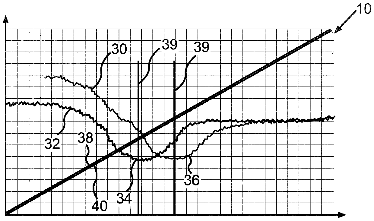
[0038] figure 1 Diagram 10 is used to determine the installation in the vehicle, in image 3 A first embodiment of the method of the actuation-induced behavior of a valve 12 for regulating the flow of a medium as a liquid is shown schematically in FIG.

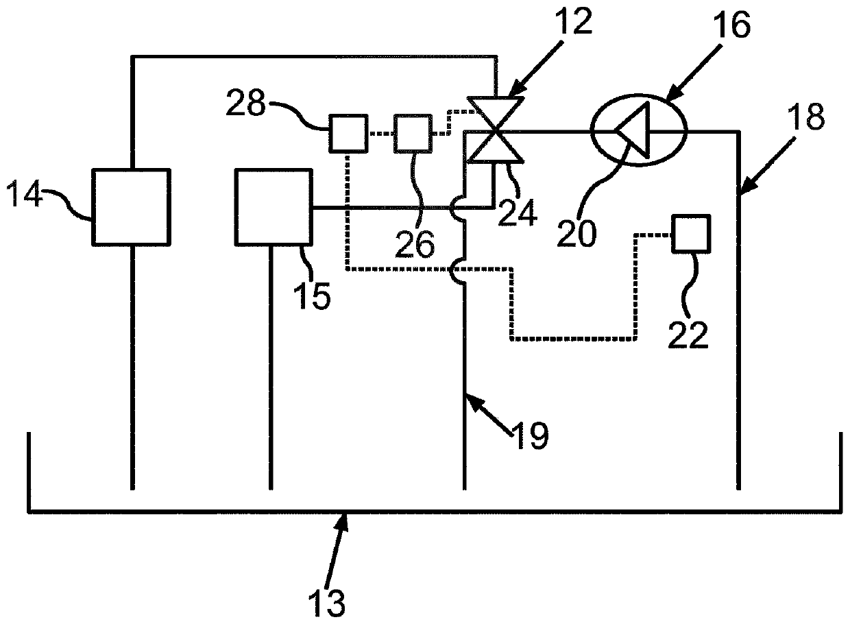
[0039] Valve 12 is used for example in image 3 In the hydraulic system of the vehicle shown schematically in . The hydraulic system has at least one hydraulic circuit 18 through which a medium can flow, the medium being oil. The hydraulic system also includes at least one pump 16 arranged in a hydraulic circuit 18 for delivering oil. Oil is conveyed by means of a pump 16 from an oil sump 13 through a hydraulic circuit 18 and from there to a valve 12 . In this case, the pump 16 has at least one pump element 20 and an electric motor 22 with which the pump element 20 is driven or can be driven. By driving the pump element 20 , oil is conveyed through the hydraulic circuit with the pump element 20 .

[0040] In order to dri...


PUM


Abstract

The invention relates to a method for determining an actuation-induced characteristic of a valve (12) installed in a vehicle for regulating the flow of a medium, the method having the following steps: and the pump (16) operation of at least one pump element (20) for conveying the medium, thereby utilizing the pump (16) to convey the medium, its mode is to utilize the motor (22) to drive the pump element (20); utilize the electronic computing device of the vehicle (28) Driving and controlling the valve (12), wherein the driving and controlling of the valve (12) is changed by means of an electronic computing device (28); during the period of conveying the medium by the pump (16) and during the change of the driving and controlling of the valve (12) is detected at least one parameter characterizing the operation of the pump (16); and determining a characteristic of the valve (12) based on the sensed parameter.

Description

technical field [0001] The invention relates to a method for determining a characteristic / state of a valve installed in a vehicle, and a vehicle. Background technique [0002] The prior art, in particular from the construction of mass-produced vehicles, discloses the use of valves in vehicles, for example automobiles, with which the flow of a medium, for example a fluid, can be regulated. Usually the valve is arranged in the corresponding line and has at least one valve element which can be adjusted or moved between at least one first position and at least one second position. In the first position, at least a partial region of the flow cross-section of the line through which the medium can flow is blocked fluidically by the valve element. In at least one second position, the valve element releases the subregion so that the medium can flow through the subregion. [0003] The valve includes, for example, an electrically drivable actuator with which the valve element can be ...

Claims


Application Information

Patent Timeline
Patent Type & Authority Patents(China)
IPC IPC(8): F16D13/72F01P11/14
CPCF01P11/14F16D13/72F01P2031/18F01P2031/20F16D2300/0214F16D25/123F01P5/12F01P7/14F01P2007/146F01P2025/60F01P2037/00F16D2500/5041
Inventor S·阿穆勒
Owner AUDI AG
Why Eureka
Try Eureka