Drive unit of a transmission

A technology for transmission units and transmissions, which is applied to transmission parts, belts/chains/gears, mechanical equipment, etc., and can solve problems such as inability to accurately adjust lubricating oil, insufficient oil supply to roller bearings, and increased wear of roller bearings.

Inactive Publication Date: 2011-06-22
GM GLOBAL TECH OPERATIONS LLC
View PDF0 Cites 0 Cited by
  • Summary
  • Abstract
  • Description
  • Claims
  • Application Information

AI Technical Summary

Problems solved by technology

Here, the oil supply to the roller bearings cannot be precisely adjusted, so undersupply of the roller bearings can occur, which leads to increased wear of the roller bearings

Method used


Image

  • Drive unit of a transmission
  • Drive unit of a transmission

Examples


Embodiment Construction

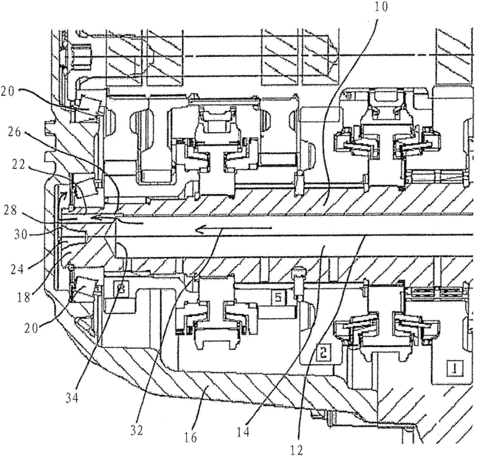
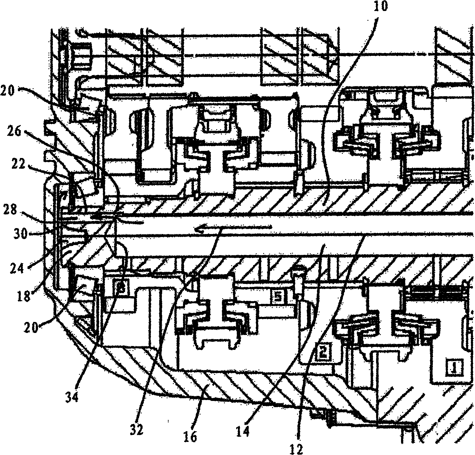
[0015] the only attached figure 1 A sectional view of a partial region of a transmission drive unit according to the invention is schematically shown. The transmission unit has a main shaft 10 with a bore 14 formed along its central axis 12 for the supply of lubricating oil. In this case, the central axis 12 of the spindle 10 corresponds to the central axis of the bore 14 . The main shaft 10 is mounted in a housing 16 , wherein this support is realized by two roller bearings 20 arranged on an end section 18 of the main shaft 10 . For the supply of lubricating oil from bore 14 , there is provided a lubricating oil supply line 22 which can transport lubricating oil from bore 14 to roller bearing 20 . The roller bearing 20 is here preferably designed as a tapered roller bearing. The central axis of the lubricating oil delivery pipe 22 is designed to be parallel to the central axis of the hole 14 , wherein the lubricating oil delivery pipe 22 is arranged on the main shaft 10 ec...


PUM


Abstract

A drive unit of a transmission includes, but is not limited to a main shaft (10). The main shaft includes, but is not limited to a bore (14) formed along its center axis (12) for the transport of lubricating oil. An oil transport line (22) is provided via which a roller bearing (20) arranged on an end section (18) of the main shaft (10) is at least indirectly connected to the bore (14).

Description

technical field [0001] The invention relates to a transmission unit of a transmission with a main shaft. Background technique [0002] The main shaft of the transmission usually has a bore formed along its central axis, through which lubricating oil can be introduced from the differential transmission to the needle bearings of the drive train and the synchronizer arranged on the main shaft. Needle bearings are only used to withstand radial forces. In addition to the needle roller bearings, at least one roller bearing is provided on the main shaft for the drive transmission and the synchronizer, which not only absorbs radial forces but also axial forces and thus provides a A support structure supported on a housing surrounding the main shaft. Roller bearings are usually supplied with oil through oil passages, by delivering lubricating oil to the roller bearings in the form of sprays to lubricate the roller bearings. In this case, the lubricating oil supplied to the roller ...

Claims


Application Information

Patent Timeline
Patent Type & Authority Applications(China)
IPC IPC(8): F16H57/04
CPCF16H57/0494F16H57/0427F16H57/0471
Inventor 霍尔格.多尔沙尔安德烈亚斯.巴里拉
Owner GM GLOBAL TECH OPERATIONS LLC
Why Eureka
Try Eureka