Rolling element bearing with cage

A technology of rolling elements and cages, applied in the direction of ball bearings, bearing elements, shafts and bearings, can solve problems such as uselessness

Inactive Publication Date: 2016-02-24
SCHAEFFLER TECH AG & CO KG
View PDF6 Cites 0 Cited by
  • Summary
  • Abstract
  • Description
  • Claims
  • Application Information

AI Technical Summary

Problems solved by technology

The resulting challenge is to prevent lubricant deposits inside rolling element bearings that are useless for lubrication and thus leave other areas requiring lubrication undersupplied

Method used


Image

  • Rolling element bearing with cage
  • Rolling element bearing with cage
  • Rolling element bearing with cage

Examples


Embodiment Construction

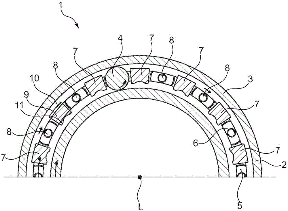
[0027] figure 1 A rolling element bearing 1 as an exemplary embodiment of the invention is shown in a schematic axial plan view, wherein only one half of the rolling bearing 1 is shown. The rolling element bearing 1 comprises an inner ring 2 and an outer ring 3 between which a plurality of balls 4 are arranged as rolling elements so that the inner ring 2 and the outer ring 3 face each other about a bearing axis L These balls roll on the raceways of rings 2 and 3 during twisting.

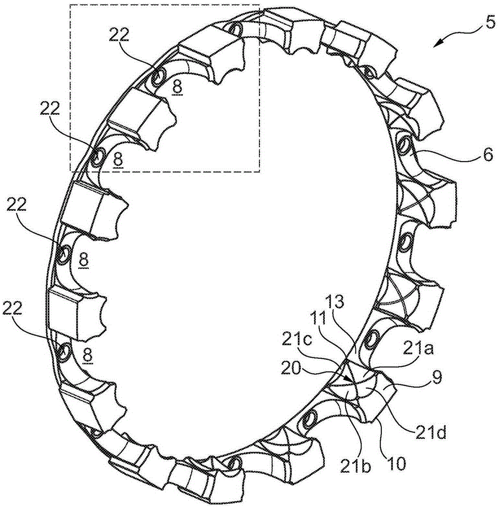
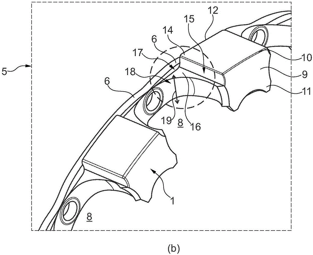
[0028] The rolling element bearing 1 comprises a cage 5, which is made of plastic. The cage 5 comprises a side ring section 6 which is designed as an annular disk extending in a radial plane perpendicular to the bearing axis L, and a plurality of web sections 7 which extend in the axial direction and are formed in the On the side ring section 6. The web sections 7 result in snap pockets 8 that are uniformly distributed in the circumferential direction, wherein each snap pocket 8 is delimited in th...


PUM


Abstract

The invention relates to a rolling element bearing (1) that comprises a plurality of balls (4) as rolling elements guided in a cage (5). In snapping pockets (8) in a region between a lateral ring section (6) and the central ball (4) track, between the ball (4) and the adjoining web section (7) and / or the adjoining lateral ring section (6), a lubricant channel (19) is formed which fluidically connects the radial outer side and the radial inner side of said cage (5). In order for the rolling element bearing (1) lubricant supply to be improved the invention suggests that, on the web sections (7), an outer block section (10) is formed on the radial outer side and / or an inner block section (11) is formed on the radial inner side, these projecting relative to the lateral ring section (6), in the radial direction in relation to the bearing axis L, and reducing the available rolling element space between two adjoining balls (4).

Description

technical field [0001] The invention relates to a rolling element bearing having the features of the preamble of claim 1 . Background technique [0002] Embodiments of ball bearings as rolling element bearings have, in many construction types, an inner ring and an outer ring between which balls are arranged in a rolling manner as rolling elements. Through the relative twisting of the inner and outer rings, the balls roll on the raceways of the rings and thus enable a relative twisting of the structure coupled to the rings. [0003] In order to keep friction losses low and at the same time increase the service life of the ball bearings, these ball bearings are usually lubricated with a lubricating medium. A possible variant of the lubrication here is permanent lubrication, wherein the rolling element bearing is equipped with a lubricant reservoir whose volume is dimensioned in such a way that it is large for the service life of the rolling element bearing. Saying is enough....

Claims


Application Information

Patent Timeline
Patent Type & Authority Applications(China)
IPC IPC(8): F16C33/41F16C33/66
CPCF16C19/04F16C33/416F16C33/418F16C33/6629F16C33/6681
Inventor 迪亚哥·巴塔利亚鲁多尼尔·库里
Owner SCHAEFFLER TECH AG & CO KG
Why Eureka
Try Eureka