Lifting rod-type ball valve

A technology for lifting rods and ball valves, which is applied to valve details, valve devices, valve housing structures, etc., can solve problems such as pipeline downtime maintenance economic losses, packing sealing material wear, and increased personnel maintenance processes, so as to save maintenance time and cost, Efficient sealing and reduced frictional resistance

Active Publication Date: 2012-10-17
SHANGHAI AUTOMATION INSTRAION CO LTD
View PDF6 Cites 10 Cited by
  • Summary
  • Abstract
  • Description
  • Claims
  • Application Information

AI Technical Summary

Problems solved by technology

After the valve has been working for a long time, as the valve stem rotates and rubs against the packing, the original packing sealing material will wear out, and the pipeline medium will leak through the gap between the valve stem and the packing structure after wear, threatening personnel. safety of life and prop

Method used


Image

  • Lifting rod-type ball valve
  • Lifting rod-type ball valve
  • Lifting rod-type ball valve

Examples


Embodiment Construction

[0028] In order to better understand the technical solution of the present invention, the following will be described in detail through specific embodiments in conjunction with the accompanying drawings:

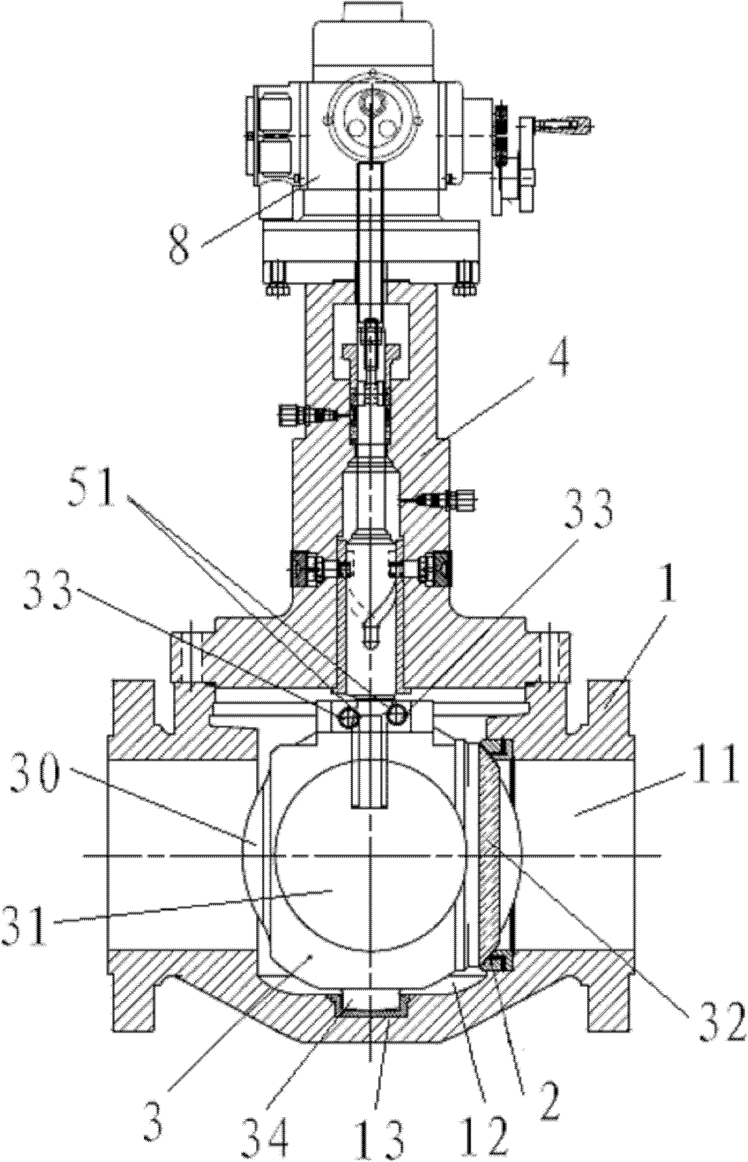
[0029] see Figure 1 to Figure 4 , The lifting rod ball valve of the present invention includes a valve body 1, a valve seat 2, a ball 3, a valve cover 4, a valve stem 5, two sets of sealing packing 6, a packing gland 7 and an actuator 8.

[0030] A coaxial fluid passage is provided at the center of the valve body 1 and the valve seat 2 .

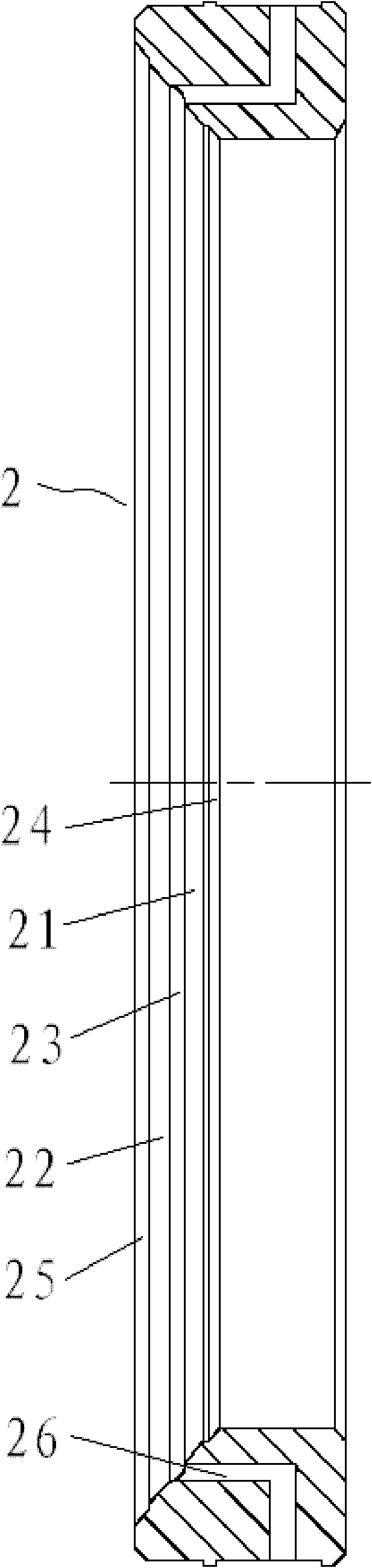
[0031] The valve seat 2 is arranged in the inner cavity of the valve body 1 and divides the fluid channel of the valve body 1 into a fluid chamber 11 and a valve chamber 12 by means of a ball 3 .

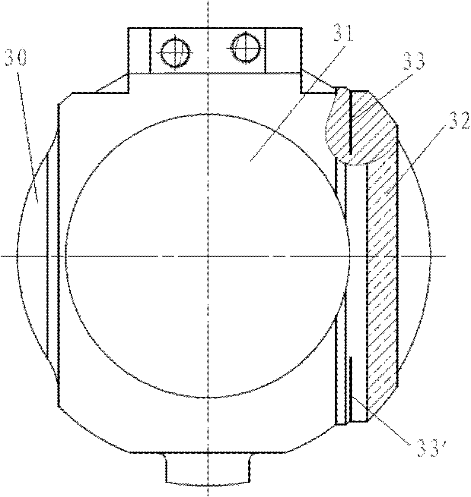
[0032] The ball 3 is movably arranged in the valve chamber 12. The ball 3 includes a ball body 30 provided with a central passage 31 and a spherical sealing ring 32. The spherical sealing ring 32 is concentrically fixed on the outer surface of...


PUM


Abstract

The invention discloses a lifting rod-type ball valve, comprising a valve body, a valve seat, a ball body, a valve cover, a valve rod, a plurality of groups of sealing fillers, a packing gland and an execution mechanism. The sealing surface of the valve seat comprises a sealing area and a supporting area. The sealing area comprises an internal sealing surface and an external sealing surface. The internal sealing surface and the external sealing surface are separated by a buffer groove. The supporting area comprises an internal supporting surface and an external supporting surface. The internal supporting surface is disposed on the inner side of the internal sealing surface. The external supporting surface is disposed on the outer side of the external sealing surface. In this way, a double-lip sealing surface is formed. The upper outer surface and lower outer surface of the ball body behind a spherical surface sealing ring are respectively cut with elastic compensation grooves which are opposite to each other and perpendicular to the axis of the sealing ring. The wall surface of a gland cavity of the valve cover is provided with a manhole. A guide cavity has a fully enclosed structure. A packing chamber is also provided with a spacer ring located in the middle of several groups of sealing fillers. A position of the corresponding spacer ring on the sidewall of a packing cavity of the valve cover is provided with a sealing greasing hole communicated with the spacer ring and equipped with a sealing grease check valve in a radial direction.

Description

technical field [0001] The invention relates to a ball valve, in particular to a lifting rod type ball valve. Background technique [0002] At present, the commonly used ball valves are mostly conventional ball valves such as fixed ball or floating ball. The valve seat is generally made of polymer synthetic materials such as polytetrafluoroethylene, nylon or rubber. These materials are affected by their own physical properties. The operating temperature of the working condition generally does not exceed 200°C, and the valve seat and the ball are easily damaged after a long period of switching. Wear leaks. Secondly, the sealing surface on the valve seat is usually a single-lip structure. Once the sealing surface of this structure is damaged by the erosion of the medium in the fluid chamber, the valve will leak, and the normal use of the valve cannot be guaranteed. The only way to repair is to replace the entire valve or valve seat, which affects the normal production of the...

Claims


Application Information

Patent Timeline
IPC IPC(8): F16K5/06F16K5/20F16K5/22F16K27/12F16K41/02
Inventor 李仲光蔡守连杨卫东蒋敏王敏华
Owner SHANGHAI AUTOMATION INSTRAION CO LTD
Why Eureka
Try Eureka