Lamp device and luminaire

A technology for lighting devices and installation parts, which is applied to lighting devices, fixed lighting devices, lighting and heating equipment, etc. It can solve problems such as difficult exporting, achieve the effects of reducing losses, improving exporting efficiency, and reducing distances

Inactive Publication Date: 2012-10-17
TOSHIBA LIGHTING & TECH CORP
View PDF5 Cites 5 Cited by
  • Summary
  • Abstract
  • Description
  • Claims
  • Application Information

AI Technical Summary

Problems solved by technology

[0008] However, if the light emitted from the LED is repeatedly reflected before reaching the lampshade, attenuation of the light will be unavoidable
As a result, it is difficult to efficiently extract the light emitted from the LED out of the lamp device.

Method used


Image

  • Lamp device and luminaire
  • Lamp device and luminaire
  • Lamp device and luminaire

Examples


no. 1 Embodiment approach

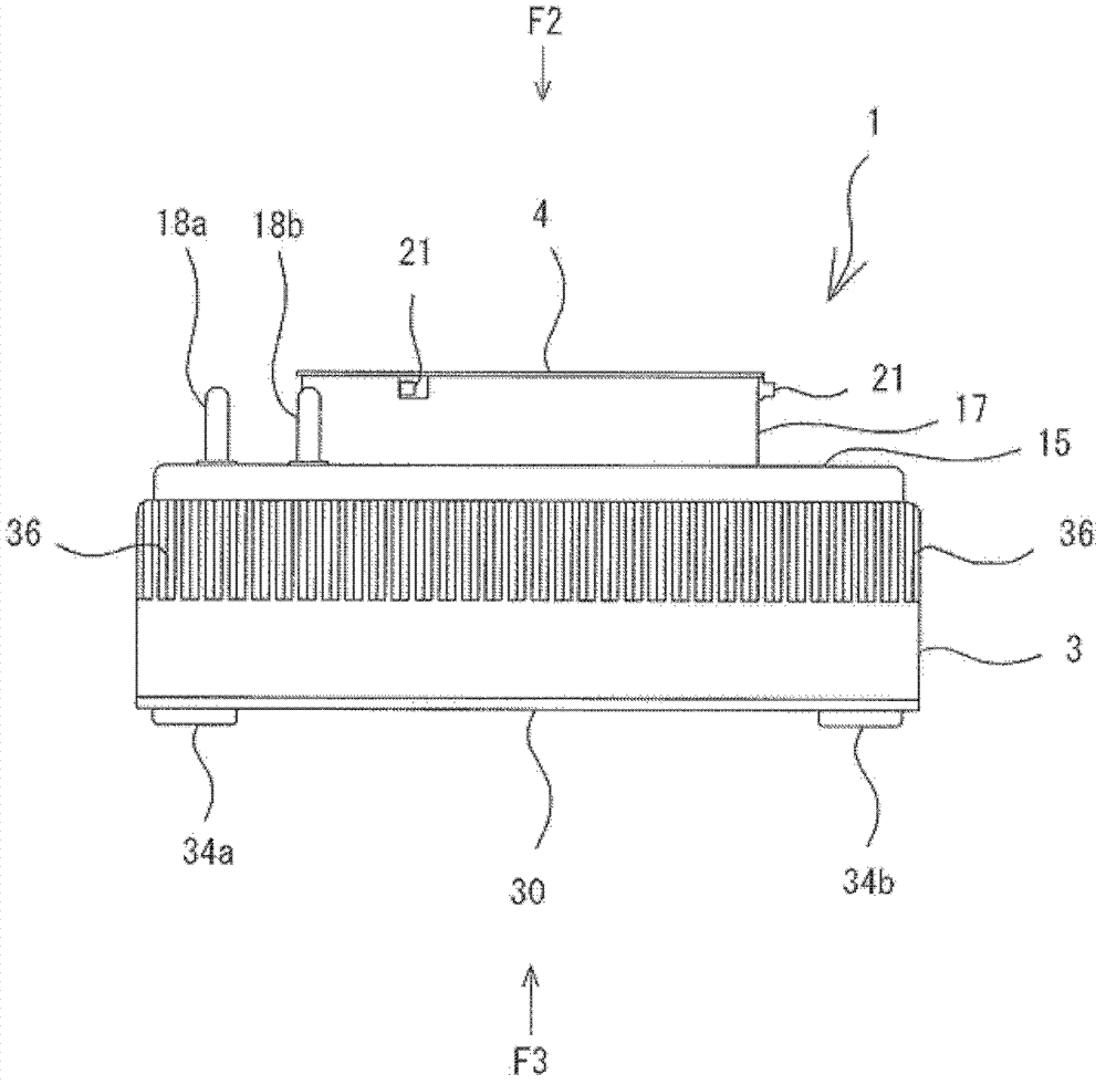
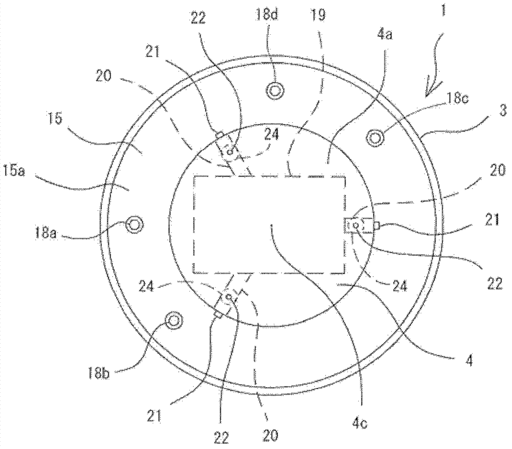
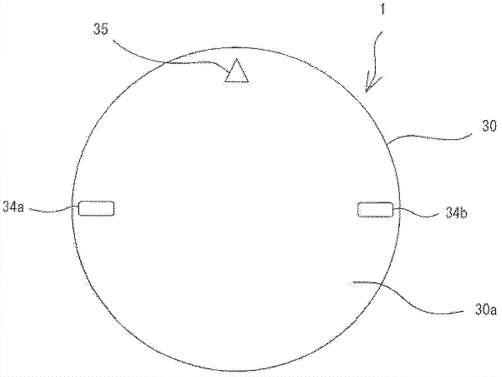
[0133] Below, refer to Figure 1 to Figure 4 The lamp device of the first embodiment will be described.

[0134] figure 1 It shows a thin lamp device 1 having a light distribution suitable for a downlight or a spotlight, for example. The lamp device 1 includes a light emitting module 2 , a main body 3 , a heat dissipation member 4 , a support member 5 , and a lighting device 6 .

[0135] The light emitting module 2 has a module substrate 7 , a plurality of light emitting diodes 8 and a sealing material 9 . The module substrate 7 is made of a metal material excellent in heat dissipation, such as aluminum. The module substrate 7 has a substantially rectangular shape and has a first surface 7 a and a second surface 7 b. The first surface 7a is covered with an insulating layer not shown. The second surface 7b is located on the back side of the first surface 7a.

[0136] The light emitting diode 8 is an example of a luminous body. The light emitting diode 8 is, for example, ...

no. 2 Embodiment approach

[0182] Figure 5 The second embodiment is disclosed. The lamp device 1 of the second embodiment has a reflector 60 housed inside the main body 3 . The configuration of the lamp device 1 other than the reflector 60 is the same as that of the first embodiment. Therefore, in the second embodiment, the same reference numerals are attached to the same components as those in the first embodiment, and description thereof will be omitted.

[0183] like Figure 5 As shown, the reflector 60 is an element for controlling the luminous intensity of the lamp device 1 . The reflection plate 60 includes a support portion 61 and a light reflection portion 62 . The support portion 61 has a cylindrical shape and is supported on the first surface 7 a of the module substrate 7 so as to surround the frame 12 of the light emitting module 2 . The reflective portion 62 has a shape expanding from one end of the support portion 61 toward the edge of the opening 14 of the main body 3 . Therefore, t...

no. 3 Embodiment approach

[0187] Image 6 as well as Figure 7 The third embodiment is disclosed. The third embodiment discloses a lighting fixture 46 using the lamp device 1 disclosed in the first embodiment or the second embodiment as a light source. In the third embodiment, the same reference numerals as those of the lamp device 1 of the first embodiment or the second embodiment are assigned to the lamp device 1 , and description thereof will be omitted.

[0188] Image 6 as well as Figure 7 The illustrated lighting fixture 46 is, for example, a down light embedded in the ceiling of a dwelling. The lighting fixture 46 includes a lamp socket 47 and a fixture main body 48 . The tool body 48 is, for example, a die-cast product made of aluminum. The tool body 48 has a substantially cylindrical shape and has a lower end 48a and an upper end 48b. A lower end 48 a of the tool body 48 defines a circular opening 49 . The inner peripheral surface 48d of the instrument main body 48 is painted in white...


PUM


Abstract

According to one embodiment, a lamp device includes a cylindrical main body (3), a light-emitting module (2), a lighting device (6) and a support member (5). The main body (3) includes an opening (14) and a heat radiating part (4) provided at an opposite side of the opening (14). The light-emitting module (2), the lighting device (6) and the support member (5) are accommodated in the body, and the light-emitting module possesses an illuminant (8). The support member (5) is thermally connected to the light-emitting module (2) and the heat radiating part (4)in a manner of transmitting the heat of the illuminant (8) to the heat radiating part (4), and accordingly, the support member (5) holds the light-emitting module (2) in the main body (3) to cause the light-emitting module (2) to be positioned in a direction closer to the opening (14) than the lighting device (6) manner.

Description

[0001] This application is based on and claims priority from Japanese Patent Application No. 2011-079076 filed on March 25, 2011, the entirety of which is incorporated herein by reference. technical field [0002] Embodiments of the present invention relate to a lamp device that emits heat emitted from a light-emitting element (light-emitting element) from a heat dissipation member, and a lighting fixture using the lamp device. Background technique [0003] Japanese Patent Application Laid-Open No. 2010-262781 discloses a flat lamp device using, for example, a GX53 type base (GX53 type base). In this kind of lamp device, the light distribution (luminous intensity distribution) is controlled in such a way that the spread of the beam (beam) becomes a middle-angle (middle-angle), so as to obtain, for example, a light suitable for a downlight (down light) or a spotlight (spot light). The light distribution. [0004] The lamp device disclosed in the said Laid-Open Patent Publica...

Claims


Application Information

Patent Timeline
Patent Type & Authority Applications(China)
IPC IPC(8): F21S2/00F21V19/00F21V17/00F21V29/00F21Y101/02
CPCF21S8/026F21V23/006F21V19/003F21Y2105/001F21V29/246F21V7/041F21V23/009F21K9/30F21V29/262F21Y2101/02F21S2/005F21V29/22F21K9/20F21V29/70F21V29/713F21V29/89F21Y2105/10F21Y2115/10
Inventor 木宫淳一户田雅宏
Owner TOSHIBA LIGHTING & TECH CORP
Why Eureka
Try Eureka